If a GNSS track appears rotated relative to a LiDAR map, inspect the heading supplied to navsat_transform_node before changing an offset. Confirm the IMU’s heading reference, the deployed node’s convention, the source selected by use_odometry_yaw, and the frame in which both tracks are compared. A rotation on a screen is not enough to identify a yaw-parameter fault.
Keep raw GNSS fixes, heading inputs, odometry, transforms and effective parameters from the same run. Then perform a documented direction test that separates an axis convention from a map-frame relationship or startup-reference problem. Preserve the original configuration so that each proposed correction has a meaningful baseline.
The LiDAR, camera and IMU calibration workflow addresses the wider sensor contract. This diagnostic focuses on earth-referenced heading entering the GNSS transformation, rather than recalibrating the entire sensor stack because two displayed paths disagree.
Identify the compared paths and frames
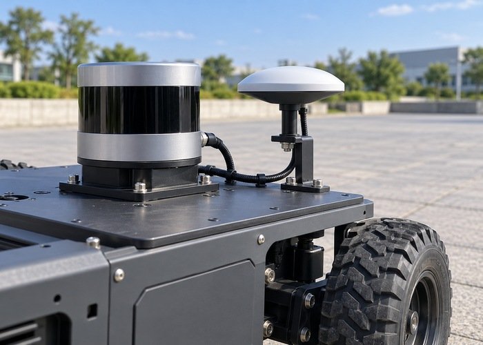
Record the raw fix topic, transformed GNSS odometry topic, LiDAR-derived pose topic, map or odometry frame, and visualization fixed frame. Identify every transformation applied before the tracks are drawn. A geographic track and a local map trajectory should not be compared as if their coordinates already share an origin and orientation.
The REP 105 frame reference distinguishes base_link, odom, map and earth roles. Use the actual published chain and documented map-to-geographic relationship. Do not force a local map to appear north-up merely to match a display preference without checking the intended frame contract.
Separate a persistent orientation mismatch from a translation offset, changing drift, or a startup jump. Retain examples that show the difference. A hypothesis about heading should predict how multiple directions transform, not only make one short straight segment overlap after manual rotation.
Write the heading contract in units and directions
The REP 103 conventions define right-handed coordinate systems, radians and geographic east-north-up axes. Record how the installed IMU’s orientation is expressed, which direction corresponds to zero yaw, and which turn direction increases its reported angle. Confirm driver behavior instead of relying on a frame label.
Inspect the orientation used by the transformation node, not only a vendor display’s compass number. The driver may publish a quaternion, a separate heading field, or a processed orientation from another estimator. Record all conversions before that value reaches navsat_transform_node, including unit changes and mounting-frame transformations.
Use a direction worksheet for known physical orientations. Establish the reference direction independently with an appropriate documented method for the test location; the LiDAR map alone is not an independent geographic heading reference. Record uncertainty in that reference rather than presenting a rough visual alignment as a precise heading measurement.
| Boundary | Record | Question to resolve |
|---|---|---|
| IMU or heading producer | Frame, zero direction, turn sign and units | Does the input follow the intended earth reference? |
| Transformation node | Version, yaw correction and selected heading source | Is a correction missing or applied twice? |
| Odometry heading | Absolute reference and estimator configuration | Is use_odometry_yaw appropriate for this source? |
| GNSS input | Raw fix, status, timestamp and frame | Is the compared signal the actual unmodified measurement? |
| World-frame output | Datum, startup sequence and frame chain | Are both paths expressed in the same intended coordinates? |
Check the deployed navsat convention
The official navsat_transform_node reference documents an east-zero yaw convention, the yaw_offset correction and a historical convention change. Check the release actually installed before interpreting an older launch file. Do not treat an offset copied from another robot as a universal correction.
Keep mounting rotation, heading-zero correction and magnetic declination conceptually separate. Determine which corrections the upstream driver or estimator already applies. Magnetic declination is relevant when the orientation is referenced to magnetic north; it should not become an unexplained tuning value used to rotate a path until it looks right.
When use_odometry_yaw is enabled, confirm that the selected odometry orientation is earth-referenced and satisfies the documented absolute-orientation requirements. A yaw estimate that simply starts at zero on each boot is not automatically an equivalent substitute. Preserve the origin and reference history of the heading estimate.
Inspect sensor preparation before tuning an offset
The official sensor-data preparation guide describes frame and input expectations for robot_localization. Check IMU mounting, orientation convention and any upstream conversion. In particular, identify whether a device-native convention was converted before publication and avoid applying that conversion twice.
Retain configuration for every estimator that contributes orientation to the selected odometry topic. Record which inputs supply absolute orientation and which represent relative or differential information. A familiar topic name is not enough to establish the origin of its heading, especially after a launch-file change or process restart.
Inspect timestamp consistency using the sensor clock-check workflow. Timing mismatch can complicate comparisons during turns. Keep an observed dynamic lag separate from a constant heading-convention error; a fixed yaw offset is not a general correction for time misalignment.
Preserve raw fixes and transformation evidence
The NavSatFix definition provides measurement time, receiver frame, fix status, geographic coordinates and position covariance context. Retain those fields alongside transformed outputs. A position fix by itself does not identify the body heading used by the transformation node.
Compare raw input and transformed output under a controlled direction sequence. Include more than one travel direction where the test method permits, and retain periods before and after initialization. Record input quality and environmental limitations instead of attributing every irregular GNSS point to the heading configuration.
Keep frame-time errors visible. The TF extrapolation diagnostic helps separate missing historical transforms from orientation interpretation. Do not replace a required timestamped transform with a latest lookup just to obtain a visually smoother comparison.
Repeat startup with a versioned worksheet
Record package versions, parameter files, datum method, startup pose, heading-source readiness, transform availability and the time the geographic-to-world relationship becomes established. A successful run after manual intervention is different from reproducible cold-start behavior. Preserve both sequences and state which one the deployment requires.
Change one justified interpretation or parameter at a time. Predict the effect on the direction worksheet before inspecting the new track. Then verify the result with observations not used to choose the correction. If a change improves one segment while reversing another, keep the contradiction visible and revisit the frame and heading assumptions.
Use the LiDAR and IMU recording checklist to preserve relevant raw messages and time context. Add raw GNSS fixes, the selected orientation source, transforms and startup logs. Replay can challenge interpretation, but it does not replace validation of live receiver behavior.
Questions to settle before accepting a heading change
Should yaw_offset always be adjusted when the map looks rotated?
No. First establish that the compared paths share the intended frame and that the input heading convention is the mismatch. A display transform, datum relationship or upstream conversion can create a similar appearance.
Can odometry heading replace an IMU heading automatically?
No. Verify the configured source and its absolute reference against the deployed node’s requirements. Relative heading that depends on the startup pose needs a different interpretation.
What should accompany an unresolved rotated-track report?
Provide the direction worksheet, raw fixes, heading source, effective parameters, frame chain and startup sequence in a reproducible support bundle. State the expected directional relationship and the observed difference without claiming that one parameter or software component is already proven responsible.