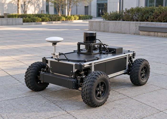
A GNSS trace can draw a small loop while a ground robot rotates almost in place. Before changing filter noise, identify which physical point each trace represents. An antenna mounted away from the rotation center really moves during a turn. The useful question is whether the reported base position still moves after the measured antenna offset has been rotated into the correct frame and removed.
For GNSS antenna offset base_link investigations, compare three separate records: the raw antenna fix, an independently observed chassis reference point, and the transformed position intended to represent the robot base. A smooth antenna arc alone does not prove a receiver fault. Conversely, a chassis that slips or pivots around a moving point cannot provide a stationary reference simply because its command contains zero forward velocity.
This workflow concerns a rigid antenna mount on a ground robot. It does not establish positioning accuracy, validate a receiver model, or replace a surveyed reference. Keep the deployed ROS distribution, receiver firmware and localization package revision with the recording. Development source cited below describes a code path to inspect, rather than a promise that every installed release behaves identically.
Start with two physical origins
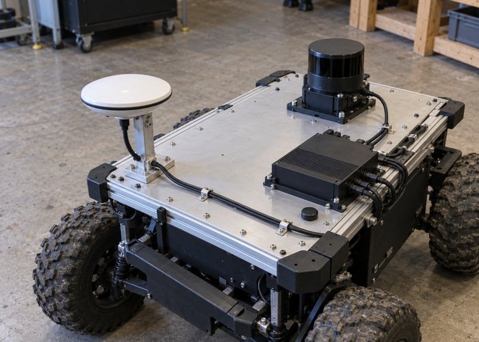
Mark the chosen chassis origin and the antenna reference point on an installation drawing. The NavSatFix message definition says its frame normally identifies the antenna location. Renaming that frame to base_link does not move the measurement to the chassis origin. If the receiver or an upstream processor already applies a lever arm, record its output reference explicitly before applying another correction.
Measure the vector from the base origin to the reported antenna point in the base coordinate system. Include forward, lateral and vertical components, along with the mounting orientation and measurement method. Follow the body axes and SI conventions in REP 103. A bracket dimension measured from a cover edge is not necessarily the antenna reference point specified by its manufacturer.
Distinguish the software origin from the actual pivot during the experiment. A differential drive robot may skid, and a steering platform may trace a circle rather than spin about its body center. The REP 105 frame definitions allow base_link to be attached at a platform-specific location. Neither the name nor a convenient CAD center proves that this point remains fixed during a turn.
Predict the antenna motion before interpreting a plot
For a rigid installation, write the geometry as p_antenna = p_base + R_world_base * r_base_antenna. Both positions must use the same world frame, and the lever-arm vector must start at the same base origin. Recovering the base position means subtracting the rotated vector. This is a geometric relationship, independent of the receiver brand and independent of whether the GNSS solution is fixed or float.
In a level planar rotation about a stationary base origin, the horizontal part of that vector sweeps an arc. Its vertical component does not set the horizontal radius. With appreciable roll or pitch, use the full orientation and three-dimensional vector instead of a yaw-only shortcut. An antenna directly above the pivot is therefore a different diagnostic case from one mounted forward on a long mast bracket.
Use the predicted arc as a hypothesis, not a fitted correction. If the raw fixes roughly follow the expected direction as heading changes, examine the compensation path. If movement changes independently of orientation, inspect the receiver environment and the independent chassis reference as well. Do not tune the lever arm until an arbitrary loop disappears: that can hide an incorrect heading input, timing error or physical chassis motion. The broader sensor calibration workflow explains why measured installation geometry should be kept separate from estimator tuning.
Record a controlled rotation with independent evidence
Begin with a stationary segment, then a slow supervised turn in a clear test area, followed by another stationary segment. Select speed, area and stopping conditions from the platform’s approved test procedure. Record raw GNSS output, converted fixes, heading or attitude, wheel odometry, local localization output, transformed GNSS odometry, TF and diagnostics. Preserve the original files before resampling or smoothing any plots.
Observe a marked chassis point with a suitable independent reference. Record whether the robot actually translated, rocked or slipped. Keep the antenna mount rigid and unchanged between trials. A repeat in the opposite rotation direction can help distinguish a repeatable geometry pattern from a time-dependent discrepancy, but it does not eliminate the need for a common clock and a known origin.
Compare values at measurement time rather than matching rows by arrival order. A correct offset rotated using a delayed attitude can leave an apparent orbit or transient. Use the checks in LiDAR, IMU and robot clock synchronization before attributing that residual to a dimension error. Keep the raw topic names and timestamp semantics in the test notes so a later replay can reproduce the pairing.
Follow the deployed compensation path
The robot_localization development implementation contains separate helpers for initial Cartesian-origin correction and subsequent world-frame robot-origin correction. The latter looks up the base-to-GNSS offset and world-to-base orientation at the requested time, rotates the offset and removes it. Missing-transform branches report errors. Inspect these exact branches in the installed revision rather than assuming a valid-looking output proves compensation succeeded.
Save the fix header frame, the configured base frame, the input odometry frame and the TF authorities. Check both the rigid mount transform and the time-dependent world-to-base path. Two broadcasters publishing competing transforms can make a diagram look connected while producing inconsistent observations. A transform available at the latest instant may still be unavailable at a fix timestamp. The TF extrapolation diagnostic provides a separate procedure for that time-coverage problem.
Also inspect the node’s input contract and startup configuration in the navsat_transform reference. Save the datum and orientation inputs used at initialization. If headings are inconsistent with the geographic frame, a geometrically correct lever arm is rotated incorrectly. Resolve that with the dedicated GNSS-to-LiDAR heading investigation instead of changing the measured mount vector to compensate.
Use observations to choose the next check
| Observation | Next check | Evidence to retain |
|---|---|---|
| Raw antenna arcs while the observed base stays still | Compare arc direction with the measured rotating lever arm | Mount drawing, attitude and unsmoothed fixes |
| Transformed base follows a similar arc | Trace compensation, frame IDs and transform availability | Installed source revision, TF and node diagnostics |
| Residual changes with rotation direction or speed | Inspect measurement-time alignment before altering geometry | Clock configuration and paired timestamps |
| Independent chassis point also moves | Separate actual translation from apparent antenna motion | Reference observations and drive commands |
| Correction appears doubled or reversed | Check upstream lever-arm processing and vector direction | Receiver output reference and transform convention |
Change one identified fault at a time and replay the same retained recording where appropriate. Compare the raw antenna trajectory, predicted antenna displacement and recovered base trajectory on common axes. Define an acceptable residual from the application’s positioning requirements and reference uncertainty before the trial; this article supplies no universal acceptance distance. A cleaner plot is supporting evidence only when its reference point and timing are known.
Questions that often arise during integration
Can a static transform alone solve the apparent movement?
A static transform supplies installation geometry. The component consuming the fix must actually use that geometry with the appropriate orientation and time. Verify the computation and its diagnostics; the existence of a TF edge alone does not demonstrate that a geographic measurement was corrected.
Should the antenna be moved to the center?
A shorter horizontal lever arm can simplify the experiment, but installation changes must respect the antenna manufacturer’s mounting requirements. Document any move as a new configuration. It does not repair an incorrect frame, stale attitude or undocumented upstream correction.
What should be sent for a reproducible review?
Send a mount sketch, reference-point definitions, exact software versions, a brief recording and the observations used to separate real motion from apparent motion. The reproducible support bundle guide provides a practical packaging approach. The final conclusion should identify the corrected data path and evidence, rather than merely report that a loop became smaller.