If a ROS camera image has swapped red and blue colors, preserve the original pixel bytes and inspect the declared encoding before changing calibration. RGB and BGR can use the same number of bytes per pixel while assigning different meanings to channel positions. Changing an encoding label without converting the underlying bytes can produce another valid-looking but incorrect image.
Start with one saved image message and a controlled color target. Record camera model, driver revision, transport, image dimensions and encoding. Compare exactly the same captured data through the producer and the failing consumer. The image-transport boundary guide addresses whether the expected image arrives; this workflow concerns how received pixels are interpreted.
The Jazzy Image message definition separates image dimensions, encoding, byte order and row length. Preserve these fields together. A screenshot discards much of the information needed to distinguish a conversion error from a driver label or buffer-layout problem.

Identify the first boundary where colors change
Compare the source capture, ROS message, decoded image and final display as separate boundaries. Record the conversion requested at each step. A display may convert data automatically, so its apparently correct image does not establish that an intermediate array uses the channel order the application expects.
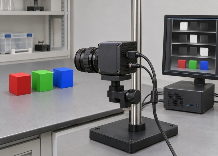
Use a stable target containing distinct red, green and blue regions under unchanged illumination. This is a diagnostic fixture, not a color-calibration reference. Avoid relying on a complex scene where a channel swap can remain visually plausible. Preserve the captured message so both consumers use identical input.
Count source messages and converted outputs separately when the conversion is embedded in a larger perception pipeline. The synchronizer diagnostic helps distinguish absent paired output from incorrect pixel interpretation. A missing callback does not demonstrate a color-encoding defect.
Read the declared encoding precisely
The official image-encoding definitions distinguish color channel order, monochrome types and Bayer patterns. Similar channel counts do not make encodings interchangeable. A generic numeric array type describes storage characteristics without necessarily carrying a complete physical color interpretation.
Record the encoding string exactly, including case and bit depth. Then compare it with the producer’s documented output and the consumer’s accepted input. Do not infer RGB from the fact that a matrix has three channels, or infer a Bayer pattern from the appearance of a grayscale preview.
For a small number of selected pixels, retain the original byte sequence and the expected channel interpretation. Compare those bytes with the values read by the consumer before display conversion. This makes the evidence reviewable without claiming that visual inspection alone proves the sensor’s color response.
| Symptom | Check first | Avoid |
|---|---|---|
| Red and blue exchanged | RGB/BGR labels and requested conversion | Relabeling bytes without conversion |
| Colored mosaic pattern | Bayer pattern and demosaicing stage | Treating raw mosaic as ordinary RGB |
| Rows appear shifted | Row step and buffer slicing | Assuming tightly packed rows |
| Only one consumer differs | Its explicit conversion path | Changing camera calibration first |
| Image is absent | Transport and callback path | Diagnosing colors before delivery |
Trace explicit conversions instead of adding swaps
List every conversion from the producer to the application. Include camera SDK output, ROS bridge, compressed transport decoder, array conversion and display library. Record both the input encoding and requested output for each stage. Two unnecessary swaps can make one path look correct while another path remains wrong.
The inspected cv_bridge C++ source provides concrete conversion behavior for that upstream revision. It is a rolling source snapshot, not a claim about every installed Jazzy package. Match the installed package revision before relying on a specific conversion or exception path.
Choose an explicit conversion at a clear boundary and document the resulting representation. Keep pass-through behavior separate from a request for a different encoding. A pass-through path should not be described as a channel-order correction unless an actual conversion occurs elsewhere.
Do not edit camera intrinsics or extrinsics to fix a color-order symptom. The raw-versus-rectified projection guide concerns geometric image domains. Channel ordering and pixel-coordinate geometry are different contracts even when the same application uses both.

Keep row layout and numeric interpretation intact
Check that the buffer length and row step agree with the image dimensions. Row padding can make a flat reshape inappropriate even when the encoding is correct. Verify the first and last selected pixel in adjacent rows so a row-stride defect is not mistaken for a channel swap.
The inspected Python bridge implementation helps trace array construction and encoding requests in that revision. Preserve whether the returned array shares storage or creates a copy in the actual application. A later in-place operation can change the reference used for comparison.
Keep byte order distinct from channel order. Byte order matters when interpreting multi-byte numeric elements, while RGB/BGR describes channel meaning. Applying one correction as though it were the other can create misleading values. Preserve bit depth and avoid an undocumented conversion to an eight-bit preview during the first diagnostic comparison.
Use the depth-image units workflow for metric depth interpretation. A depth representation is not a color image merely because both arrive as sensor_msgs/Image. Do not transfer assumptions about units, invalid values or display scaling between them.
Treat Bayer data as its own processing boundary
Determine whether the incoming data is already a processed color image or a raw color-filter-array mosaic. If demosaicing is required, establish the declared Bayer pattern and the stage that applies the conversion. Cropping or an incorrect producer label can change the interpretation that a later stage assumes.
The official cv_bridge project introduction describes its role between ROS images and OpenCV representations. Use the installed implementation and camera documentation to determine supported conversions. A general bridge capability does not establish that an arbitrary raw sensor format is supported.
Preserve the original mosaic and the processed image as different artifacts. Compare conversion inputs, output dimensions and selected regions. Do not declare a raw sensor defective because an application displayed the mosaic without the intended processing stage.
Validate the corrected path with saved data
Repeat the original comparison with unchanged bytes and one documented conversion change. Verify selected pixel values and the controlled target’s channel interpretation. Keep any image-quality evaluation separate, because a correct channel order does not establish white balance, exposure quality or calibrated color accuracy.
Repeat after a normal startup and after any driver or bridge update. Save the effective encoding and conversion request, rather than only the package name. The sensor-calibration workflow becomes relevant once the representation is correct and geometric alignment still needs qualification.
Store the captured message, metadata, conversion chain, installed revisions and corrected observations in a reproducible support bundle. State exactly where the interpretation changed. This avoids passing an undocumented extra channel swap to the next application maintainer.
Frequently asked questions
Can I change bgr8 to rgb8 in the header?
Only if that label already describes the bytes correctly. Otherwise the representation needs an actual conversion, not just a new label.
Does a correct preview prove the array is RGB?
No. The preview library may apply a conversion. Inspect the array and its declared representation before display.
Is a Bayer image simply a three-channel color image?
No. Establish the mosaic pattern and supported demosaicing stage before treating its output as ordinary color channels.