GMSL frame sync can coordinate camera frame timing on a supported hardware and software path, but it does not by itself prove that camera exposure and LiDAR acquisition share the same time reference. Verify the trigger path, the meaning of each timestamp, and the clock relationship before treating a fusion overlay as capture-alignment evidence.
Separate trigger generation, exposure, sensor readout, transport, driver timestamping, host arrival, and application use. Those events can occur at different times. An Ethernet packet arriving beside a camera buffer in one host callback does not establish simultaneous acquisition, and identical camera timestamps do not establish their accuracy relative to a LiDAR clock.
The GMSL and Jetson BSP compatibility checklist establishes the proposed integration path. This article addresses a later qualification task: determining which capture events are aligned, how that alignment is measured, and what remains uncertain for camera-LiDAR processing.
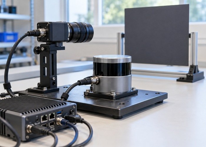
Pin the supported trigger topology
Record compute module, carrier revision, BSP, camera framework, camera module and firmware, serializer, deserializer, link assignment, and the path that supplies frame sync. Include connector and signal-routing documentation provided for the exact integration. Do not assume an exposed connector pin, a driver parameter, or a similarly named feature has the same behavior on another board.
NVIDIA’s versioned SIPL GMSL architecture overview describes frame-sync modes driven externally from the SoC or by the deserializer oscillator in that framework. Treat those modes as documentation for that release and supported topology, not proof that an older Jetson camera stack exposes the same configuration.
For an older deployment, compare the applicable Jetson GMSL camera framework reference with the installed drivers and hardware. Keep release-specific procedures separate. A working capture endpoint or virtual-channel route does not automatically demonstrate a working frame-trigger distribution path.
Identify each physical camera independently before timing tests. The virtual-channel routing diagnostic helps rule out duplicated or swapped streams. Comparing two copies of one stream can create deceptively close timestamps without showing that two sensors are synchronized.
Write an event and timestamp contract
| Event | Question to answer | Evidence to request or collect |
|---|---|---|
| Frame-sync edge | Which device generates it and which inputs receive it? | Supported topology, effective mode and documented observation point |
| Camera acquisition | What exposure event does the timestamp represent? | Sensor mode and driver timestamp definition |
| LiDAR acquisition | Is the stamp a point, scan boundary or another event? | Model-specific timing contract and preserved point times |
| Host arrival | When did the software receive the payload? | Identified receive clock and transport context |
| Fusion lookup | Which pose and time does the consumer request? | Frame chain, lookup time and application configuration |
Give every timestamp a unit, clock domain, epoch or offset origin, and event meaning. Record whether the implementation copies a device timestamp, translates it into host time, or assigns a new time during processing. Leave unknown fields explicit instead of silently treating all values named timestamp as interchangeable.
The CameraInfo definition associates its header with image acquisition and the camera optical frame. Verify how the installed driver implements that contract and whether metadata corresponds to the image actually consumed. A header convention alone is not a measurement of trigger-to-exposure delay or clock conversion accuracy.
Keep frame triggering distinct from clock synchronization
Determine how each sensor’s clock relates to the reference used by the fusion application. Camera-to-camera triggering and camera-to-LiDAR clock mapping are separate questions. A LiDAR should only be described as using a trigger or synchronization input when the documentation for that exact model and firmware supports that mode.
The ROS 2 clock-and-time design distinguishes system, steady, and ROS time. Do not subtract unrelated clock values and report the result as capture skew. Document the conversion or synchronization relationship first, including its initialization and behavior across a device or host restart.
Use the sensor clock-check workflow to structure that investigation. Include the clock source used by recorders and replay consumers. A live test and a replay test can use different time behavior even when they contain the same images and points.
Observe timing at the earliest supported boundary
Where the integration provides documented test points and procedures, collect evidence that the intended trigger reaches the intended camera path. Record the instrument setup, reference clock, measured event, and limitations. Electrical trigger evidence answers a narrower question than whether each exposure began at the expected moment.
Request or collect evidence for the sensor’s exposure relationship under the selected mode. Record exposure settings, frame period, shutter mode, automatic control state, and any setting that can change acquisition behavior. Avoid treating a configuration checkbox as equivalent to measured capture timing.
Then characterize host arrival separately under the required workload. Queues, readout, transport, and processing can change arrival timing without changing the original trigger relationship. Preserve acquisition-related metadata alongside receive observations so that a delay introduced later is not incorrectly attributed to the sensor’s capture phase.
Use controlled motion to challenge the claimed alignment
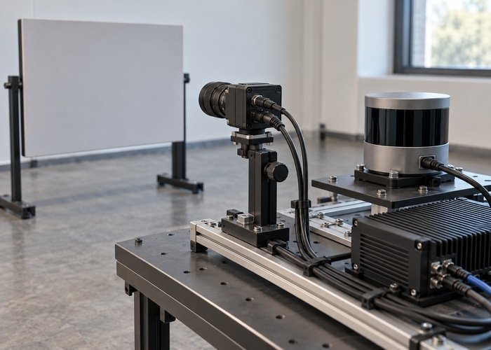
Begin with a stationary asymmetric scene to confirm routing, geometry, and the projection path. Check frame conventions using the camera optical-frame diagnostic. A rotated or incorrectly projected overlay should be corrected before using moving edges to reason about timing.
Next use a repeatable, controlled target sequence appropriate to the sensors and test area. Record the target’s motion or event reference independently where the test method requires it. Define what observation distinguishes an extrinsic error from a time offset; a single attractive frame is weak evidence for either.
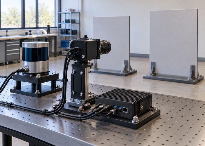
Repeat the capture with different relevant directions and operating conditions while keeping the interpretation method fixed. Report the observed range of results and the measurement method rather than presenting an unexplained single offset. Derive acceptance limits from the application requirements and evidence, not a universal synchronization tolerance.
Validate the consumer’s temporal interpretation
The official tf2 time tutorial distinguishes a transform at a requested timestamp from the latest available transform. Inspect the actual fusion lookup. A synchronized sensor pair can still be projected using a pose from the wrong time if the consumer substitutes a latest transform or mixes image and cloud reference events.
Preserve the original image timestamps, LiDAR timing fields, transforms, configuration, and reference observations with the LiDAR timing recording checklist. State whether a cloud stamp represents one acquisition boundary while individual points span an interval. Do not discard per-point timing and later claim that one cloud-level stamp proves every point aligned with one exposure.
Repeat the required startup and reconnect cases. A system can look aligned after settling while using an uninitialized clock relationship immediately after boot. Keep the old and new clock identities, trigger configuration, and application sequence visible in the acceptance record so that another engineer can reproduce the result.
Questions to settle before claiming synchronization
Do equal camera timestamps prove alignment with LiDAR?
No. Establish what those values represent and how their clock maps to the LiDAR clock. Equal numbers can result from a shared assignment policy without independently proving simultaneous acquisition.
Can host arrival times replace acquisition timing?
Only for a task explicitly defined around arrival events. They include later transport and processing effects, so they do not by themselves establish sensor capture alignment.
What should the final qualification record say?
Name the supported topology, trigger mode, measured events, clock relationship, retained data, uncertainty and acceptance conditions. State which claims were demonstrated and which remain vendor-dependent. That is stronger evidence than describing an entire sensor system as synchronized because one frame-sync setting was enabled.