
Mechanical LiDAR sensors are engineering marvels built for laboratories — but the demands of Level 4 autonomy are systematically exposing every fragility they carry.
At the core of every spinning LiDAR unit sits a stack of high-speed rotating mirrors, motors, and precisely aligned optical assemblies cycling thousands of times per minute. Each revolution introduces micro-stress into bearing surfaces. Each pothole transmits shock loads directly into optical alignment tolerances measured in micrometers. In a controlled R&D environment, these are manageable inconveniences. Deployed across a robotaxi fleet running 20 hours a day through urban grids — they become catastrophic liability.
Mechanical fatigue doesn’t degrade gracefully; it compounds silently until a sensor fails mid-route.
The automotive-grade vibration standard (AEC-Q101) exposes what the industry sometimes calls the “spinning bucket” problem. A sensor that performs flawlessly on a test track begins accumulating alignment drift after sustained road vibration. What follows is an expensive recalibration cycle — technicians manually realigning optical stacks that have shifted fractions of a millimeter, enough to corrupt point cloud accuracy by meters at range. According to IEEE Spectrum, solid-state LiDAR technology eliminates this failure mode entirely by removing mechanical wear from the architecture — a direct consequence of its non-rotating design, which significantly increases Mean Time Between Failure (MTBF) for commercial fleets.
The math doesn’t favor mechanical systems at scale. Multiply recalibration downtime across hundreds of vehicles, factor in motor replacement intervals, and the operational cost curve bends sharply upward. As explored in the tradeoffs of 360-degree sensor designs, broader coverage from spinning units comes at a durability cost that fleet operators increasingly can’t absorb.
The question, then, isn’t whether mechanical LiDAR works — it’s whether its architecture can survive the physics of production autonomy. The answer points directly toward the semiconductor-based designs reshaping the sensor landscape.
Solid-State Architecture: From Moving Parts to Semiconductors
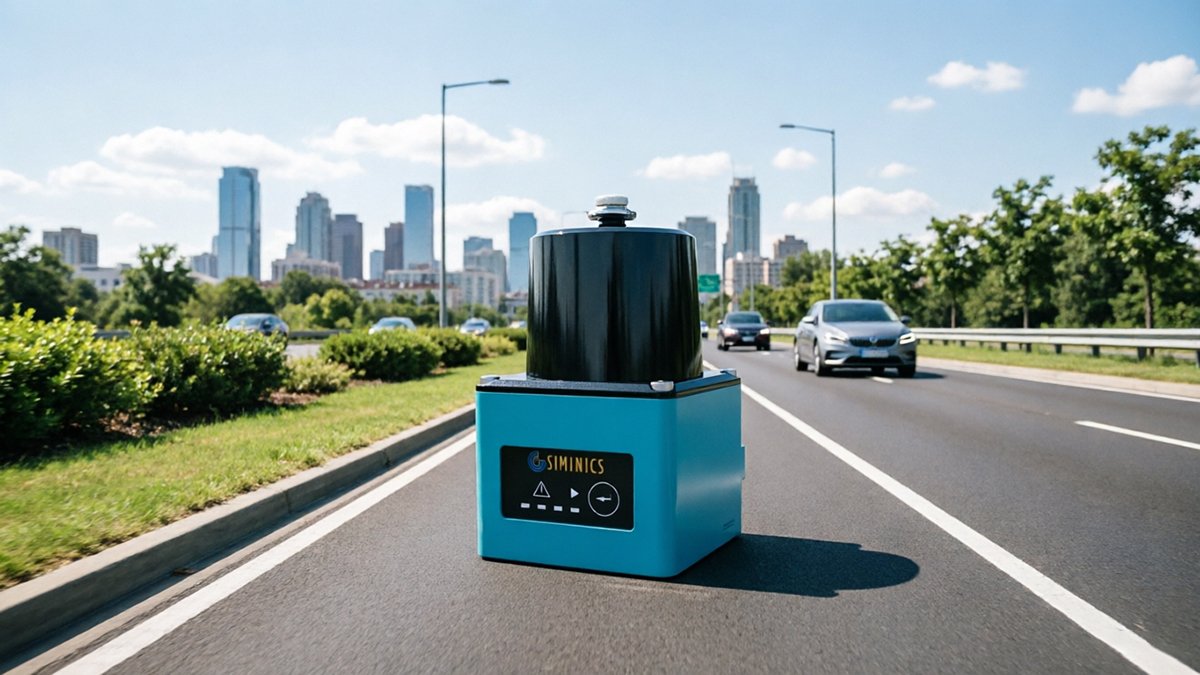
The core distinction in the solid-state LiDAR vs mechanical LiDAR debate is architectural: solid-state sensors contain no macroscopic moving parts whatsoever, replacing physical rotation with silicon-level beam steering.
True solid-state design means the entire scanning mechanism lives on a chip — a fundamental shift that unlocks manufacturing economics impossible to achieve with spinning mirror assemblies.
Two primary approaches define how solid-state sensors map depth:
- Optical Phased Arrays (OPA): Steer laser beams electronically by shifting the phase of light across an array of emitters. Phase-based beam steering eliminates every motorized element while enabling precise, programmable scan patterns. The tradeoff is complexity in phase calibration at scale.
- flash LiDAR: Rather than scanning point by point, this simultaneous illumination approach floods the entire scene with a single laser pulse, capturing the full depth map in one shot. This dramatically simplifies the optical path and reduces latency.
CMOS fabrication is the manufacturing engine behind both approaches. Because solid-state LiDAR components are produced using the same photolithography processes as consumer electronics, they follow dynamics analogous to Moore’s Law — yield improves, die size shrinks, and per-unit cost falls with each process generation. According to Deloitte Insights – Automotive Sector, solid-state LiDAR systems can achieve a 10x reduction in manufacturing complexity compared to mechanical counterparts, enabling rapid mass production.
In practice, this means the painstaking sub-micron optical alignment required in mechanical sensor assembly — a primary cost and failure driver — is replaced by high-yield silicon fabrication. A process that once demanded skilled technicians working under cleanroom conditions becomes a standard semiconductor fab run.
That durability advantage extends well beyond the factory floor, as the next section examines through the lens of real-world road punishment.
The ‘Shaker Test’ and Real-World Automotive Durability
Real-world roads are durability stress tests that separate laboratory sensors from deployable L4 hardware — and mechanical LiDAR consistently fails them.
Vibration tolerance is the primary killer of mechanical perception stacks. Spinning mirror assemblies and bearing systems are precision-calibrated to micron tolerances. Continuous road vibration — even at low amplitudes — introduces micro-wobble that corrupts point cloud accuracy and accelerates bearing wear. A pothole isn’t just a comfort issue; for a sensor with thousands of moving parts, it’s a cumulative structural attack. SAE International notes that “the shift to solid-state technology is not just about size; it’s about the vibration and shock tolerance required for automotive-grade reliability.”
Thermal management compounds the problem in fundamentally different ways for rotating versus stationary housings. Mechanical sensors generate concentrated heat at motor windings and slip rings — components that require airflow paths and thermal buffers that conflict with sealed, weatherproof enclosures. Solid-state designs distribute heat across a semiconductor die, enabling simpler passive or active cooling integrated directly into the vehicle chassis. In extreme cold, lubricants in mechanical bearings thicken, degrading spin-up consistency and scan rate before the sensor ever takes a reading.
Shock events — sudden impacts from gravel roads, speed bumps, or debris strikes — represent a catastrophic single-point failure risk for rotating assemblies. A mechanical sensor can lose calibration permanently from a single high-G impact; a solid-state sensor with no moving parts has no calibration drift vector to disrupt. This physics advantage is why automotive-grade solid-state designs are targeting AEC-Q101 and ISO 26262 certification standards — thresholds mechanical sensors structurally struggle to meet.
Understanding how solid-state sensors survive these stressors leads directly to a deeper question: which solid-state architecture — flash lidar vs scanning lidar — best handles the speed and latency demands of L4 obstacle detection?
Flash vs. Scanning: Navigating the Solid-State Taxonomy
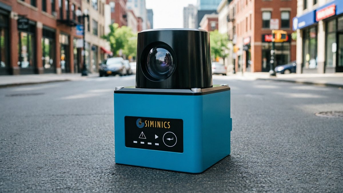
Not all solid-state LiDAR is built the same — and in the expanding solid-state LiDAR market, the Flash vs. scanning distinction shapes everything from sensor placement to system latency.
flash LiDAR works like a camera strobe: a single laser pulse illuminates the entire field of view simultaneously, and a 2D detector array captures depth data in one global-shutter snapshot. According to research published in photonics literature, this instantaneous illumination is critical for high-speed obstacle detection — there’s zero inter-pixel time lag, meaning a vehicle crossing at highway speed appears geometrically consistent rather than motion-distorted. The trade-off is power density: flooding a wide field demands significantly more energy, and range typically tops out sooner than scanning alternatives.
Scanning solid-state systems — primarily MEMS mirrors and Optical Phased Arrays (OPA) — take the opposite approach. Rather than illuminating everything at once, they electronically steer a focused beam across the scene in a controlled pattern. This concentrates energy along each ray, enabling longer detection ranges and finer angular resolution. OPA goes furthest, steering light through phase modulation with zero mechanical components whatsoever.
| Attribute | flash LiDAR | MEMS / OPA Scanning |
|---|---|---|
| Data capture | Simultaneous global shutter | Sequential beam steering |
| Range | Shorter (~50–100 m typical) | Longer (150 m+) |
| Resolution | Limited by detector array size | Higher, tunable |
| Power draw | Higher per frame | Lower per point |
| Latency | Near-zero | Slight scan-cycle delay |
The core insight: neither technology is universally superior — L4 stacks often fuse both, using flash sensors for close-range, low-latency reaction and scanning units for long-range scene modeling. The real competitive pressure isn’t architectural anymore. It’s economic — and that pressure is now coming overwhelmingly from one direction.
The China Factor: How Mass Production is Crashing the Price Barrier
Chinese manufacturing has fundamentally reset the global price floor for the self-driving car LiDAR sensor — and the ripple effects are reshaping procurement strategies worldwide.
The core shift is simple: high-performance LiDAR is rapidly becoming a commodity. What cost $75,000 per unit in the experimental era is now approaching the sub-$500 range, with reports suggesting costs are trending toward the $200 mark as Chinese volume manufacturing scales aggressively. That’s not incremental improvement — it’s a structural price collapse.
“Automakers are racing to put China-made LiDAR in next-generation cars as costs drop toward the $200 mark.” — Autoblog / Reddit Research
Domestic EV manufacturers are leading this integration push. Budget-conscious EV platforms are shipping with factory-installed solid-state LiDAR as a standard feature — not an expensive option — demonstrating that perception hardware is now viable at consumer price points. This changes the calculus for how spatial awareness gets built into vehicles from the ground up, rather than retrofitted as a premium add-on.
“The price trajectory of solid-state LiDAR mirrors what happened to camera modules — once manufacturing scales, the cost floor drops faster than most legacy suppliers can respond.” — Industry analyst perspective
Procurement strategy is shifting in response. Automakers and Tier 1 suppliers are increasingly moving toward direct-factory sourcing platforms to eliminate intermediary markups that once added 30–60% to unit costs. In practice, bypassing traditional distribution channels compresses lead times and creates tighter integration feedback loops between hardware teams and sensor manufacturers.
The broader implication is competitive pressure across the entire supply chain — and it sets up a critical question about how fleets deploy multiple sensor types together.
Blind Spot Compensation and the Multi-Sensor L4 Strategy
Autonomous driving L4 reliability isn’t achieved with a single sensor — it’s built through layered, redundant perception that leaves no zone unmonitored.
A primary long-range lidar unit, whether forward-facing or roof-mounted, inevitably creates near-field dead zones. Objects within 3–5 meters of the vehicle — a pedestrian stepping off a curb, a bollard at low speed — fall outside its optimal detection band. This is where solid-state sensors earn their place in the stack: not as replacements for the main unit, but as precision gap-fillers embedded at corners, bumpers, and flanks.
In practice, a well-architected L4 perception wrap combines multiple sensor types across distinct placement zones:
- Forward long-range unit — solid-state or hybrid, handling 200m+ detection for highway and urban through-traffic
- Corner-mounted blind spot sensors — short-range solid-state units covering the near-field gaps at vehicle sides and rear quarters
- Rear-facing coverage — low-profile solid-state panels protecting against closing threats during reversing or low-speed maneuvering
- Redundant overlapping fields — adjacent sensors whose FOVs intentionally overlap, ensuring no single-point failure removes coverage
LidarStar’s catalog includes specialized blind compensation sensors engineered specifically to eliminate near-field gaps common in L4 prototypes — a detail that matters when multi-sensor fusion architecture is being designed from the ground up.
Data fusion is where the real engineering challenge lives. Syncing multiple solid-state inputs — each with different scan timing, point density, and coordinate origin — into a single coherent point cloud demands tight hardware synchronization and robust software pipelines. Timestamp misalignment as small as a few milliseconds introduces ghost artifacts at highway speeds.
Redundancy isn’t optional at L4; it’s the certification baseline. Regulatory frameworks increasingly require demonstrated failover, making overlapping sensor zones a structural requirement rather than a design preference. How those sensors are sourced, however, is a question the industry is still working out.
Procurement Evolution: Direct-Factory vs. Traditional Tier-1s
How you source solid-state LiDAR sensors matters almost as much as which sensor you choose — and the traditional automotive supply chain is increasingly the wrong answer for L4 development teams.
Traditional Tier-1 procurement is a bottleneck. Legacy automotive supply chains were built for high-volume, low-iteration production cycles — not the rapid hardware-software co-development that defines modern autonomy programs. Lead times stretch across quarters, MOQs lock teams into bulk commitments before validation is complete, and markup layers compound the cost at every handoff. For a robotaxi startup or a university autonomy lab working on 3D LiDAR integration, that model creates friction exactly where speed matters most.
Direct-factory procurement removes those friction points entirely. Key advantages include:
- Pricing transparency — no distributor margins inflating already-pressured hardware budgets
- 24-hour technical support — direct access to engineers who understand the sensor’s firmware, calibration behavior, and edge cases
- Faster iteration cycles — smaller order quantities enable real-world testing without capital lock-in
- Replacement guarantees — structured assurance programs that protect deployment timelines
Quality validation remains a legitimate concern in a value-tier market. The responsible countermeasure is triple-certified assurance — sensors verified against automotive, industrial, and performance-grade standards simultaneously — rather than treating low price as a proxy for low quality.
LidarStar operates precisely in this gap: direct-factory pricing on certified high-performance sensors, paired with global support infrastructure. For Western engineering teams working with hardware from leading manufacturers, that bridge eliminates the translation cost — technical, logistical, and financial.
Taken together, these procurement shifts don’t just reduce cost. They compress the timeline from sensor selection to validated deployment — which, as the next section will make clear, is the defining competitive variable in L4 development right now.
The Bottom Line: Key Takeaways for L4 Development
The transition to semiconductor-based LiDAR is the final hardware hurdle for consumer-ready autonomous driving — and the decisions engineers make today will determine which programs reach mass deployment first.
Having covered multi-sensor architectures, procurement strategy, and the cost economics driving this shift, the core conclusions are straightforward:
- Mechanical LiDAR is legacy hardware for L4 programs. Rotating assemblies with hundreds of moving parts were an acceptable proof-of-concept tool. For production-scale deployment, they’re an engineering liability. Solid-state is not an upgrade — it’s the mandatory successor. Understanding why mechanical designs once dominated makes the case for moving past them even more compelling.
- MTBF and vibration tolerance are your primary selection criteria. A sensor that delivers exceptional point-cloud resolution but fails under road vibration or thermal stress is operationally useless in a Robotaxi fleet. According to comparative durability analysis, solid-state designs offer dramatically superior resistance to shock and mechanical fatigue — the baseline requirement, not a bonus feature.
- The $200–$500 price point is no longer aspirational — it’s achievable. Scaling Robotaxi fleets with multi-sensor configurations only makes commercial sense at this cost tier. Programs still budgeting around legacy sensor pricing are building on a flawed economic model.
- Direct-factory procurement is the fastest path to fleet scale. Cutting traditional Tier-1 intermediaries reduces lead times, lowers per-unit costs, and gives engineering teams direct access to firmware and calibration support.
In practice, the programs advancing most confidently toward L4 commercialization share one common trait: they’ve already committed to solid-state. If specific technical questions remain — about sensor topologies, weather performance, or range tradeoffs — those are worth examining closely before finalizing any hardware specification.
Frequently Asked Questions: Solid-State LiDAR in L4
The fastest way to clear up confusion around solid-state LiDAR is to address the questions engineers and program managers ask most often before committing to a sensor architecture.
Flash vs. OPA LiDAR — what’s the real difference?
flash LiDAR illuminates the entire field of view simultaneously, like a camera flash, making it fast and mechanically simple but power-hungry at longer ranges. Optical Phased Array (OPA) steers a laser beam electronically by controlling the phase of light across an array of emitters — no moving parts, ultra-compact, but currently limited in output power. Both are solid-state; they differ in how they scan. Learn more about flash LiDAR architecture.
Why is solid-state cheaper to manufacture?
The answer comes down to assembly. Mechanical sensors require precision motors, bearings, and manual alignment during production. Solid-state designs integrate laser and detector arrays onto standard semiconductor wafers, enabling the same high-volume fab processes that drive down smartphone chip costs — a structural cost advantage, not an incremental one.
Can solid-state sensors handle highway speeds?
Range anxiety is legitimate but increasingly outdated. Leading digital solid-state sensors now demonstrate 200+ meter detection at highway-relevant closing speeds, which satisfies the reaction-distance requirements for L4 highway operation.
How does weather affect each type?
In practice, both technologies face degradation in heavy rain or dense fog — physics doesn’t discriminate by form factor. However, solid-state sensors with no exposed rotating optics maintain better seal integrity, reducing ingress risk over time.
The solid-state pivot isn’t a future trend — it’s an active engineering mandate. If your L4 program hasn’t audited its sensor stack against current solid-state capabilities, now is the time to start.