
Mechanical LiDAR systems have a fundamental problem — they spin. In high-vibration environments like autonomous forklifts, industrial drones, and highway-speed vehicles, that rotation becomes a liability. Bearings wear. Alignment drifts. Calibration degrades the moment a sensor takes a hard knock on a loading dock or an unpaved road. For applications where perception failure isn’t an option, that’s an unacceptable engineering compromise.
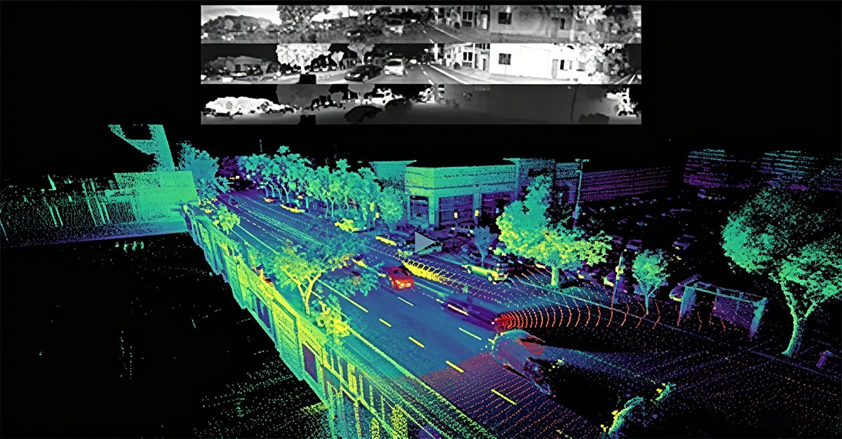
The shift toward solid-state LiDAR is no longer a future roadmap item — it’s a 2025 operational requirement.
The rise of AI for Science (AI4S) initiatives has made this urgency sharper. Machine learning models trained on point cloud data demand consistency. A jittered or mechanically distorted scan introduces noise that propagates through the entire perception stack, degrading object detection confidence exactly when it matters most. Clean, repeatable spatial data isn’t just preferred — it’s the foundation these models are built on.
This is precisely where solid-state LiDAR architecture reframes the conversation. As IEEE Xplore notes, removing moving parts drastically increases Mean Time Between Failures (MTBF), making automotive-grade reliability achievable at scale. Manufacturing hubs like Shanghai are already accelerating this transition, producing solid-state units at volumes that are steadily driving costs toward consumer-viable price points. For teams building systems that depend on reliable 3D depth data, the mechanical era is closing.
Flash LiDAR sits at the center of this shift — functioning as the “global shutter” equivalent for depth sensing. But understanding why that distinction matters technically requires a closer look at how scanning and flash architectures actually diverge.
Flash LiDAR vs. Scanning LiDAR: A Technical Divergence
As established, the mechanical design of spinning sensors creates real-world vulnerabilities. But the gap between scanning and solid-state technology isn’t just about moving parts — it runs deeper, into the fundamental logic of how each system collects data.
Scanning LiDAR builds a 3D picture sequentially, firing laser pulses one point at a time as the sensor rotates. By the time a full scan completes, the scene has already changed. In high-speed environments — think an autonomous forklift rounding a corner at speed — that temporal lag produces motion distortion: objects appear stretched or displaced from their actual positions.
Flash LiDAR, by contrast, illuminates the entire scene simultaneously with a single broad laser pulse, capturing every data point in one unified moment. According to NASA, this non-scanning approach eliminates motion blur entirely, a critical advantage in fast-moving robotics applications. The difference isn’t incremental — it’s architectural.
Solid-state flash LiDAR doesn’t reconstruct a scene over time — it captures reality as a single, synchronized snapshot, making it the only sensor architecture that truly matches the speed of autonomous decision-making.
The enabler behind this capability is the global shutter. Unlike rolling shutters that expose pixels sequentially, a global shutter exposes all pixels at the exact same instant, ensuring perfect temporal synchronization across the entire depth image. There’s no inter-frame skew, no partial-exposure artifact — just clean, time-consistent 3D data.
Frame rate performance underscores the advantage further. Research published in Scientific Reports confirms flash LiDAR systems routinely achieve 30Hz to 100Hz frame rates, far outpacing mechanical scanners that often struggle to exceed 20Hz while maintaining point density.
| Mechanism | Data Capture | Reliability | Best Use Case |
|---|---|---|---|
| Scanning LiDAR | Sequential, point-by-point | Prone to vibration failure | Slow-speed mapping |
| Flash LiDAR | Simultaneous, full-scene | No moving parts | High-speed robotics, AGVs |
For engineers evaluating sensor stacks — and you can explore a broad range of 3D sensing options for industrial robotics — the frame rate and synchronization gap matters enormously when integrating sensor data into AI-driven decision pipelines. Which is exactly where the conversation naturally leads next.
The Role of Flash LiDAR in AI for Science (AI4S)
The hardware improvements covered in the previous sections don’t exist in a vacuum. High-fidelity solid-state sensing is rapidly becoming the data backbone for a broader movement — AI for Science (AI4S) — where machine learning models demand clean, consistent, real-world inputs to function reliably at scale.
Data Integrity: Why ‘Clean’ Sensor Data Wins
Machine learning models are only as good as the data used to train them. Time-of-flight LiDAR, particularly the flash variant, captures entire scenes in a single pulse — no frame stitching, no motion artifacts, no gaps from vibration-induced misalignment. That consistency is exactly what AI training pipelines need.
- Pixel-level depth accuracy reduces labeling errors in training datasets
- Global shutter capture eliminates rolling shutter distortion that corrupts point clouds
- Uniform spatial sampling across frames improves model generalization
- Fewer preprocessing corrections mean faster pipeline throughput
In practice, data scientists working on industrial automation models report significantly lower outlier rejection rates when sourcing point cloud data from solid-state sensors compared to spinning alternatives.
Predictive Modeling: Feeding the AI Pipeline
High-resolution 3D data enables predictive maintenance models to detect sub-millimeter structural changes in machinery over time. The General Purpose Intelligent LiDAR Sensor research highlights how software-configurable sensors can adapt output parameters on the fly — a critical feature when AI models require varying resolution or range settings during different operational phases.
- Real-time volumetric mapping supports anomaly detection algorithms
- Consistent frame rates synchronize with edge-compute inference cycles
- Structured 3D outputs reduce dependency on secondary sensor fusion
Clean sensor data isn’t a preference for AI systems — it’s a prerequisite.
Global Trends: Shanghai’s AI4S Industrial Push
The 2025 AI for Science White Paper from the Shanghai Institute for AI for Science identifies high-precision environmental sensors as foundational infrastructure for the next generation of automated manufacturing. China’s industrial regions are actively integrating AI4S frameworks into factory operations, creating strong demand for solid-state LiDAR hardware that meets rigorous data quality standards. You can explore how solid-state systems are reshaping mapping to understand how this trend extends beyond factory floors.
- AI4S adoption in manufacturing accelerated significantly between 2023 and 2025
- Industrial automation deployments increasingly require sensor-agnostic, ML-ready data formats
- Government-backed hardware initiatives are prioritizing solid-state over mechanical systems
This global alignment between AI research priorities and sensor hardware quality sets the stage for an important spatial question — not just what sensors capture, but where they’re looking. That leads directly to one of the most practical challenges in autonomous systems: coverage gaps.
The ‘Proximity Bubble’: Solving the Blind Spot Problem
The previous sections established how flash LiDAR accelerates AI-driven science and autonomous decision-making. But one of its most underappreciated advantages isn’t measured in meters — it’s measured in centimeters. Specifically, the critical zone immediately surrounding a vehicle or robot that traditional sensors routinely miss.
According to SAE International, flash LiDAR is uniquely suited for short-range and blind spot detection due to its wide vertical and horizontal Field of View (FoV) — a capability that scanning alternatives fundamentally struggle to match at close range.
Wide FoV as a Defensive Perimeter
When comparing flash lidar vs scanning lidar for proximity awareness, the architectural difference becomes immediately practical. A spinning sensor sweeps in narrow horizontal slices, which means nearby objects in the vertical periphery can fall between scan lines entirely. Flash LiDAR, by contrast, illuminates the entire scene simultaneously — wrapping the sensor in a dense, real-time perimeter of depth data with no temporal gaps. Think of it as the difference between a flashlight sweep and a floodlight.
“Wide field of view sensing around a vehicle isn’t a luxury feature — it’s the geometric foundation of safe operation in unpredictable, close-quarters environments.”
Flash LiDAR for AGVs in Tight Spaces
Automated Guided Vehicles (AGVs) operating in warehouse aisles face a uniquely punishing geometry. Narrow corridors, fast-moving workers, and dynamic shelf configurations demand instantaneous spatial awareness within a two-to-five-meter bubble. The absence of moving parts in solid-state designs means consistent near-field resolution on every single frame — no missed pulses, no vibration-induced drift. You can explore how different sensor types compare for close-quarters environments in more depth.
Blind Spot Compensation in L2+ Systems
In L2+ autonomous driving, blind spot zones around the A-pillar, rear quarter panels, and vehicle underbody represent statistically significant collision risks. Flash LiDAR’s simultaneous full-scene capture closes these gaps in ways that scanning architectures simply can’t replicate without adding multiple overlapping sensor units — which multiplies cost and integration complexity. Pairing 3D forward-facing sensors with wide-FoV flash units creates full-spectrum coverage that handles both long-range highway detection and the messy, close-range reality of urban environments.
Knowing where to deploy flash LiDAR is one challenge. Knowing how to integrate it effectively into your system is another — which is exactly what the next section addresses.
Implementation Guide: Integrating Solid-State Sensors
Understanding the theory behind flash lidar technology is one thing—deploying it successfully is another. Whether you’re outfitting a mobile robot, an autonomous vehicle, or a research platform, the integration process demands deliberate hardware evaluation and supply chain awareness. Here’s a practical five-step framework to get it right.
1. Evaluate Your Architecture: ToF vs. Other Solid-State ApproachesTime-of-Flight (ToF) captures the entire scene in a single illumination pulse, making it ideal for high-speed environments where motion blur is unacceptable. Alternative solid-state methods, such as FMCW or structured light, offer their own trade-offs in range resolution and cost. Benchmark each against your specific latency and range requirements—for robotics beyond 50 meters, ToF-based flash systems consistently outperform, as demonstrated in NASA’s autonomous navigation research.
2. Audit Power Consumption Early Mobile robotics budgets are tight on wattage. Flash sensors typically draw lower average power than spinning mechanical units because illumination is pulsed rather than continuous. Request detailed SWaP (Size, Weight, and Power) datasheets before committing to a platform—this single step prevents costly redesigns downstream.
3. Prioritize Factory-Direct Technical Support R&D timelines don’t survive slow support queues. Working directly with manufacturers accelerates firmware customization, calibration, and integration troubleshooting. For teams exploring a broader sensor portfolio for their builds, factory-direct access means faster iteration cycles and clearer upgrade paths.
4. Navigate the Global Supply Chain Strategically According to LidarStar Market Analysis, triple-certified hardware and direct factory pricing are now standard for robotics procurement across 26+ countries. Sourcing through Shanghai-based manufacturing hubs with established export compliance reduces lead times dramatically.
5. Validate with Real-World Scene Tests Before full deployment, stress-test your sensor against worst-case scenarios—high-speed passes, cluttered near-field zones, and low-reflectivity surfaces.
Pro-Tip: Always request a raw point cloud sample from your vendor under your specific operating conditions. Processed demos can mask limitations that only appear at full operational speed.
These steps set a solid foundation—and the results become far more compelling when you see the data visualized directly.
Visualizing the Future: Flash LiDAR in Action
The implementation steps outlined above make more sense once you see flash LiDAR’s output firsthand. The video below demonstrates a 940nm global shutter flash LiDAR system capturing dense, motion-blur-free point clouds in real time.
Watch for two things: how the entire scene populates instantaneously without sweep artifacts, and how fast-moving objects retain sharp geometric definition—something scanning-based systems simply can’t guarantee at equivalent speeds.
Flash LiDAR doesn’t just reduce motion blur—it eliminates the exposure window where blur originates.
That distinction becomes critical when comparing technologies side by side. In high-speed environments, scanning sensors smear edge geometry across dozens of milliseconds; flash captures the same frame in a single synchronized pulse. The difference isn’t incremental—it’s architectural. As you’ll see in the video, point cloud fidelity holds even as subjects accelerate through frame.
Still have questions about range limits, sunlight interference, or how flash compares to MEMS-based alternatives? The next section addresses the most common technical questions directly.
Frequently Asked Questions
Is flash LiDAR only suited for short-range applications?
Not at all—this is one of the most persistent misconceptions in the field. Modern flash LiDAR systems operate at ranges well beyond 200 meters, as demonstrated by 940nm global shutter implementations already in use for autonomous navigation. Range performance depends on pulse power, wavelength selection, and detector sensitivity—factors that continue to improve rapidly across the industry.
How does solid-state design improve MTBF exactly?
Mean Time Between Failures (MTBF) rises dramatically when you eliminate rotating mechanical parts—bearings, motors, and slip rings that wear under continuous operation. Solid-state flash LiDAR has no moving components, which removes the primary failure mode that limits traditional spinning units in high-vibration environments. According to Advanced Scientific Concepts, this architecture makes flash LiDAR particularly durable in demanding aerospace and defense applications.
Can flash LiDAR operate reliably in direct sunlight?
Yes, with the right design choices. Operating at 940nm—where solar irradiance is significantly lower—combined with narrow bandpass optical filters allows flash LiDAR to reject most ambient solar noise. Sense Photonics’ 940nm system was specifically engineered with this challenge in mind, demonstrating robust outdoor performance.
What separates flash LiDAR from MEMS LiDAR?
MEMS LiDAR still uses a physically moving micro-mirror to scan point by point, making it a scanning architecture—just miniaturized. Flash LiDAR, by contrast, illuminates the entire scene simultaneously with no scanning motion whatsoever. That distinction matters enormously for high-speed applications: flash captures a complete 3D frame in a single pulse, whereas MEMS systems accumulate points sequentially. For teams evaluating sensors across different autonomy tiers, understanding this architectural gap is essential before committing to a platform.
Key Takeaways
- Pixel-level depth accuracy reduces labeling errors in training datasets
- Global shutter capture eliminates rolling shutter distortion that corrupts point clouds
- Uniform spatial sampling across frames improves model generalization
- Fewer preprocessing corrections mean faster pipeline throughput
- Real-time volumetric mapping supports anomaly detection algorithms