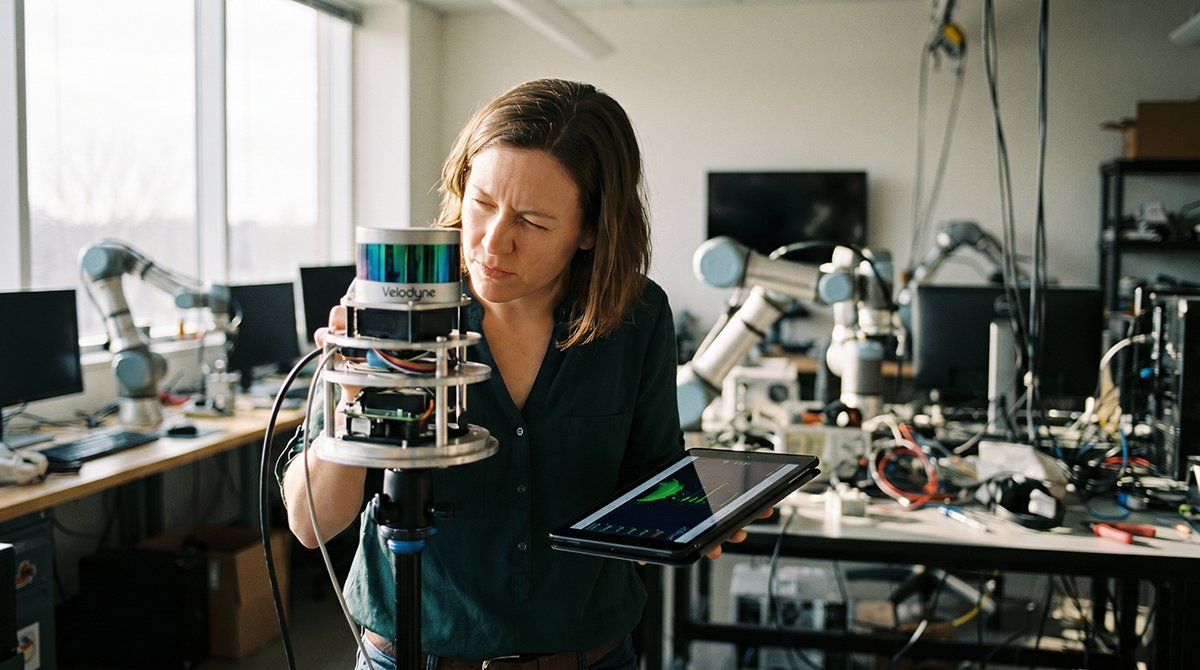
A robot that can’t see a child’s outstretched arm or a shopping cart handle isn’t navigating — it’s gambling. For decades, 2D LiDAR served adequately in controlled, predictable spaces: warehouse aisles, factory floors, mapped corridors. But those environments are vanishing from the R&D roadmap. The real frontier is messy, human-centric, and three-dimensional.
“The transition from 2D to 3D perception is the single most important leap for robots operating in unstructured human environments.” — Robotics Business Review
Height-blindness is the core technical failure of 2D sensors. A traditional 2D LiDAR scans a single horizontal plane — typically ankle- to knee-height — and builds a flat obstacle map from that slice of the world. What it misses is everything above or below that plane. A table overhanging a clear floor, a protruding shelf bracket, a raised forklift arm — none of these register until contact occurs. In high-speed R&D applications, that contact isn’t a near-miss. It’s a failure condition, a damaged asset, or a safety incident.
Unstructured environments compound the problem exponentially. Unlike a mapped warehouse, spaces like hospital corridors, retail floors, research labs, and outdoor campuses are defined by constant, unpredictable change. Humans crouch, lean, and reach. Objects are placed temporarily at arbitrary heights. Door frames exist at one elevation while glass panels extend above them invisibly. A sensor architecture built around a 2D horizontal slice was never designed for this variability — and research on 2D LiDAR limitations confirms it lacks the spatial resolution to categorize objects by shape, volume, or vertical profile.
3D forward-facing sensors bridge this gap by capturing full volumetric data in the direction of travel. For developers building the next generation of lidar for autonomous vehicles and autonomous mobile robots, this shift isn’t incremental — it’s architectural. The move from planar scanning to point cloud generation redefines what a robot can understand about the space ahead of it.
That understanding starts at the physics level — specifically in how 3D LiDAR converts light into precise distance data across an entire scene.
Decoding the 3D LiDAR Point Cloud: Precision Beyond Pixels
3D LiDAR doesn’t guess distances — it measures them directly, making it fundamentally more reliable than any pixel-based perception approach for high-speed autonomous systems.
Time-of-Flight (ToF) principle: Every pulse of laser light fired by a LiDAR unit has a round-trip timer. The sensor emits a beam, it strikes a surface, and the reflection returns. Multiply that elapsed time by the speed of light, divide by two, and you have an exact range reading — no inference, no estimation. Scale this across millions of pulses per second across multiple vertical scan layers, and the result is a dense lidar point cloud: a precise, three-dimensional map of every surface within sensor range, refreshed in real time.
Point cloud density and object categorization are tightly linked. A sparse return of 16 vertical channels might outline a rough shape, but a 64- or 128-channel system resolves the subtle geometry that distinguishes a pedestrian’s upright silhouette from a cyclist’s forward lean and rotating limb pattern. In practice, this granularity lets classification algorithms operate with far higher confidence — a critical factor when a decision must be made in under 100 milliseconds at highway speed. You can explore how density shapes sensor selection in unstructured environments for a deeper breakdown.
Direct measurement vs. pixel estimation is where the gap becomes undeniable. Camera systems derive depth by comparing pixel disparity between two lenses or by training neural networks on known object sizes — both methods introduce compounding error at range. LiDAR returns an absolute distance value per point, independent of lighting, contrast, or model assumptions.
The safety payoff is measurable. According to Insurance Institute for Highway Safety research, 3D LiDAR systems reduce false positives in emergency braking by up to 50% compared to camera-only or radar-only setups — fewer unnecessary stops, fewer rear-end collisions triggered by phantom detections.
That reliability depends heavily on the sensor’s mechanical architecture, which brings us to a critical design question: what happens to performance when you remove the moving parts entirely?
The Rise of Solid-State and MEMS LiDAR Architectures
Solid-state lidar is redefining what’s possible in autonomous perception by eliminating the mechanical vulnerabilities that made earlier sensors impractical for production environments.
MEMS (Micro-Electro-Mechanical Systems) LiDAR uses microscopic mirrors etched onto silicon chips to steer laser beams — no external spinning motors required. True solid-state designs go further, using optical phased arrays or flash illumination to scan an entire field of view simultaneously, with zero moving parts at any scale.
Why this matters in high-vibration environments:
- Mechanical spinning units rely on precision-balanced rotating assemblies that degrade under continuous vibration, road shock, and temperature cycling
- MEMS designs reduce mechanical stress points dramatically, since the only moving elements are microscopic and silicon-mounted
- True solid-state units have no mechanically vulnerable components whatsoever, making them far more resilient on high-speed test vehicles and industrial platforms
Aerodynamic and integration advantages are equally significant. Traditional roof-mounted spinning sensors create substantial drag and require custom housing solutions that compromise vehicle aesthetics and airflow. Forward-facing solid-state sensors integrate flush into bumpers, grilles, or headlight assemblies. According to a McKinsey & Company Automotive & Assembly Report, this architectural shift meaningfully improves vehicle aerodynamics and sensor longevity compared to traditional mechanical spinning units — a finding that’s accelerating OEM adoption across high-speed AV programs.
MTBF (Mean Time Between Failure) is where the operational argument becomes undeniable. Mechanical sensors operating at highway speeds accumulate rotational wear that shortens service intervals and introduces failure modes at the worst possible moments. Solid-state and MEMS platforms project dramatically longer operational lifespans, reducing maintenance overhead and increasing data continuity across long-duration test campaigns. For teams logging thousands of miles monthly, that reliability gap translates directly to program costs and timeline confidence. Explore how sensor selection shapes autonomy outcomes across different deployment scenarios.
That durability foundation also supports another critical capability — consistent performance at the detection ranges where high-speed safety margins are actually made or lost.
Long-Range Detection: The 200-Meter Safety Threshold
At high speeds, perception range isn’t a feature — it’s the foundation of every safety decision an autonomous system makes.
Physics of reaction time sets a hard lower bound on how far ahead a vehicle must “see.” At highway speeds of 70 mph, a vehicle travels roughly 103 feet per second. Factor in algorithm processing latency, actuator response, and braking distance, and a full emergency stop can consume 150–200 meters of road. That means any object appearing inside that window is already a collision risk before the system has fully responded. 200 meters is therefore the minimum detection threshold, not an aspirational target.
Forward-facing LiDAR achieves this range more effectively than 360-degree spinning units precisely because of how it concentrates optical energy. By narrowing the field of view to a forward cone — typically 60°–120° horizontal — the sensor allocates more pulses per angular unit, dramatically improving point density at long range. The result is maintained signal-to-noise ratio even when return pulses carry only a fraction of the transmitted energy. According to a Velodyne LiDAR white paper cited by SAE International, forward-facing LiDAR sensors can detect objects with high precision at distances exceeding 200 meters, even in low-light conditions — a benchmark that camera-based systems routinely fail to match after dusk.
Low-light performance is where the gap between LiDAR and traditional vision sensors becomes most significant. Cameras depend entirely on ambient photons; LiDAR generates its own. This active illumination approach means performance stays consistent from noon to midnight, in fog, and under glare conditions that blind image-based systems entirely.
Braking distance integration is where 3D lidar mapping translates raw range data into actionable safety margins. The reconstructed point cloud doesn’t just flag object presence — it encodes distance, velocity (via multi-return analysis), and trajectory, feeding directly into the planning layer with centimeter-level accuracy. For Level 4 autonomy development, this fidelity is non-negotiable.
Getting this data reliably is only half the challenge — integrating it efficiently into a broader sensor stack is what the next section addresses.
Integrating 3D LiDAR into the Modern Perception Stack
Effective autonomous perception isn’t built on a single sensor — it’s the product of a carefully orchestrated multi-modal stack where each input fills the gaps of another.
In a mature sensor fusion architecture, 3D LiDAR provides the spatial ground truth that cameras and radar alone cannot deliver. As noted by research in deep learning sensor fusion, cameras supply rich semantic color data while LiDAR anchors every detection to precise three-dimensional coordinates. Radar contributes velocity measurements in adverse weather, but lacks the resolution to define object boundaries. The result is a layered workflow:
- Camera input → semantic classification (object type, lane markings, traffic signs)
- MEMS lidar → dense point cloud for spatial localization and depth accuracy
- Radar returns → velocity vectors and all-weather range confirmation
- Fusion layer → unified scene representation fed to the planning stack
Computational load is the honest challenge that perception engineers face when scaling this approach. High-density 3D point clouds — often exceeding 100,000 points per frame at 20 Hz — demand significant onboard processing. Efficient architectures increasingly rely on sparse convolution networks and pillar-based encoding to reduce compute overhead without sacrificing accuracy, a design direction explored in depth by researchers working on efficient 3D perception.
Standardized data formats are equally critical for integration velocity. ROS2 compatibility has become a near-universal requirement in R&D environments, enabling teams to swap sensor hardware without rewriting middleware pipelines. Alongside format standardization, AI-driven models benefit from fine-tuning on diverse perception datasets — including instruction-tuned datasets like oaast_sft_zh — which help models generalize across varied driving environments and edge cases. For teams tracking how lidar has evolved from prototype to production, the convergence of open-source tooling and standardized interfaces has dramatically compressed integration timelines.
With the perception stack defined, the next practical challenge becomes sourcing the hardware itself — and the procurement landscape carries its own set of engineering and budgetary trade-offs worth examining closely.
Overcoming the Procurement Barrier: Automotive Grade vs. Budget Constraints
Sourcing high-performance 3D forward-facing sensors has historically been one of the steepest barriers for R&D teams working outside of Tier 1 automotive budgets.
The middleman markup problem is real — traditional distribution chains add layers of cost that can price serious hardware out of reach for smaller labs and startups.
The cost challenge. In practice, procurement through regional distributors or third-party resellers can inflate sensor pricing by 20–40% above factory cost. For teams running lean R&D budgets, that delta often determines whether a prototype moves forward at all. Every dollar absorbed by intermediaries is a dollar not spent on iteration.
Why automotive-grade certification actually matters. It’s tempting to substitute consumer-grade hardware to cut costs, but for industrial robotics applications, the trade-off can compromise the entire test program. Automotive-grade LiDAR is designed to withstand continuous vibration, wide operating temperature swings (typically –40°F to 185°F), and harsh ingress conditions — all verified through ISO and IATF certification frameworks. According to LidarStar Market Analysis, triple-certified hardware meeting ISO/IATF standards is now becoming accessible to small-scale R&D labs through global procurement platforms — a meaningful shift from even five years ago.
The direct-to-factory model. One practical approach gaining traction is bypassing regional distribution entirely and sourcing directly from certified manufacturers. This eliminates intermediary margins while maintaining full access to factory documentation, warranty coverage, and calibration data. Teams exploring high-channel-count options like those reviewed in this technical breakdown of advanced LiDAR configurations are increasingly using direct procurement to make professional-grade hardware viable within constrained budgets.
Global logistics as an equalizer. International shipping platforms and streamlined customs processes have effectively democratized access to sensors that were once restricted to well-funded OEM programs. A robotics lab in the Midwest can now procure the same IP67-rated, vibration-tested hardware used in commercial vehicle fleets — at factory pricing.
That accessibility is reshaping what’s possible at the prototype stage, and it’s only one piece of how the broader LiDAR landscape is evolving.
Future Outlook: The Road to Ubiquitous 3D Perception
3D LiDAR is no longer a premium research tool — it’s becoming the baseline infrastructure for any autonomous system that needs to survive the real world.
The next wave of innovation centers on perception stack optimization at every layer, from sensor hardware to edge inference. Here’s where the industry is heading by 2030:
- AI-on-chip integration will move inference directly into the sensor housing, reducing latency and offloading processing demands from the central compute stack. Rather than streaming raw point clouds, future units will transmit pre-classified object data.
- Blind-spot compensation arrays will work in tandem with forward-facing units, creating seamless 360-degree coverage without requiring a full rotating mechanical sensor — a major step for compact urban robots and delivery vehicles.
- Real-time cloud-synced mapping will allow individual vehicles to contribute to and pull from continuously updated 3D map layers, dramatically improving performance in dynamic environments like construction zones and crowd-dense areas.
Cost curves are following a trajectory similar to early camera modules. The China AI Series White Paper 2023 notes that 3D spatial data is expected to become the next frontier for multimodal LLM training — a signal that demand for high-quality point cloud datasets will accelerate hardware commoditization. As volume scales, the unit economics for solid-state LiDAR improve sharply, opening the door to consumer-level robotics applications such as lawn automation, home delivery, and personal mobility devices. You can explore how MEMS-based sensing is already bridging this gap in platforms targeting mass-market deployment.
In practice, the sensor and the compute are converging into a single intelligent node. As explored in efficient 3D perception research, reducing computational overhead without sacrificing spatial resolution is the critical engineering challenge defining this decade.
The strategic implications of all this — for procurement, system design, and safety thresholds — are worth distilling into clear action points.
The Bottom Line: Key Takeaways for Robotics R&D
3D forward LiDAR has crossed the threshold from competitive advantage to non-negotiable requirement for any R&D team operating at the edge of autonomous performance. As covered throughout this article, the gap between 2D and 3D perception isn’t incremental — it’s architectural. Here’s what that means in practice:
- 3D perception is mandatory in unstructured environments. 2D scanners operate on a single horizontal plane, leaving height-based hazards — overhanging obstacles, road debris, uneven terrain — entirely invisible. As noted in AGV applications research, this blind spot isn’t a minor limitation; it’s a collision waiting to happen. No 2D system can protect against what it cannot detect.
- Solid-state and MEMS architectures are the reliability standard. Mechanical spinning sensors were a necessary first step, but moving parts introduce failure modes that don’t belong in production-grade deployments. MEMS-based designs — like those found in automotive-grade solid-state platforms — deliver vibration tolerance and sensor longevity that mechanical units simply can’t match.
- 200 meters is the minimum safety threshold at highway speeds. At 60 mph, a vehicle travels roughly 88 feet per second. Detection ranges below 150–200 meters compress reaction time to an unworkable window, making extended range a physics requirement, not a spec sheet luxury.
- Direct procurement is now the cost-effective path. Automotive-grade sensors are accessible at R&D-compatible price points. Teams that bypass distribution markups and source directly gain both margin and faster iteration cycles — a decisive advantage when development timelines are tight.
- According to LidarStar Technical Consulting, 3D LiDAR is the only sensor delivering direct, high-precision time-of-flight distance measurement at scale — no inference, no estimation, just raw spatial truth.
Together, these principles form a clear decision framework: build your perception stack on 3D, choose solid-state for durability, validate at 200-meter range, and procure smart. If specific implementation questions remain — from sensor behavior in adverse weather to SLAM integration — the next section addresses the most common queries engineers face when adopting 3D forward LiDAR.
Frequently Asked Questions About 3D Forward LiDAR
3D forward LiDAR sits at the intersection of optics, robotics, and real-time compute — and these five questions capture what R&D teams ask most often.
What is the difference between 3D mechanical and solid-state LiDAR?
Mechanical LiDAR uses a spinning assembly of laser emitters and detectors to generate a full 360° point cloud, offering wide field-of-view coverage at the cost of moving parts and higher failure rates. Solid-state designs eliminate the rotating mechanism entirely — using MEMS mirrors, optical phased arrays, or flash illumination — delivering greater durability and lower production cost. If you’re evaluating long-term architectural tradeoffs, hybrid approaches that blend both paradigms are gaining traction for forward-facing sensor stacks.
How does 3D LiDAR perform in heavy rain or fog?
LiDAR significantly outperforms cameras in low-light conditions, but heavy precipitation introduces real challenges. Water droplets scatter near-infrared laser pulses, generating false returns that inflate the point cloud with noise. According to LidarVision Technical Specs, performance in adverse weather requires specific wavelength filtering strategies — a limitation sensor fusion architectures are designed to compensate for by blending LiDAR with radar returns.
Can 3D forward LiDAR be used for SLAM?
Yes — and it’s one of the most compelling use cases. LiDAR-based SLAM algorithms like LeGO-LOAM and LIO-SAM use successive point cloud registration to build and update maps in real time, making 3D LiDAR ideal for GPS-denied environments such as warehouses, tunnels, and underground facilities.
Why is 200m range necessary for autonomous vehicles?
At highway speeds of 65 mph, a vehicle travels roughly 95 feet per second. A 200m detection range provides approximately 6.5 seconds of decision time — the minimum threshold for safe braking and path replanning at speed.
How do I integrate LiDAR point clouds into ROS2? Most modern 3D LiDAR units publish data as sensor_msgs/PointCloud2 messages over a ROS2 driver node. From there, packages like PCL (Point Cloud Library) handle filtering, segmentation, and object detection pipelines within a standard ROS2 workspace.