A mirrored or rotated 2D LiDAR scan can originate in the relationship between angle metadata and the range array. Before rotating the robot model or reversing a buffer, establish which physical direction each array index represents. A scan can contain plausible distances while assigning them to incorrect bearings.
Keep the robot stationary and record asymmetric targets at known directions relative to the sensor. Compare those observations with the original LaserScan message, then with the transformed display and downstream consumer. The purpose is to locate the first incorrect representation, rather than change several settings until a familiar outline appears.
This workflow concerns planar scan indexing and metadata. It does not establish ranging accuracy or diagnose every mapping failure. Save the exact sensor model, firmware, driver revision, configuration and consumer version. Development code cited below illustrates specific computations to inspect; it is not a universal configuration for every scanner.
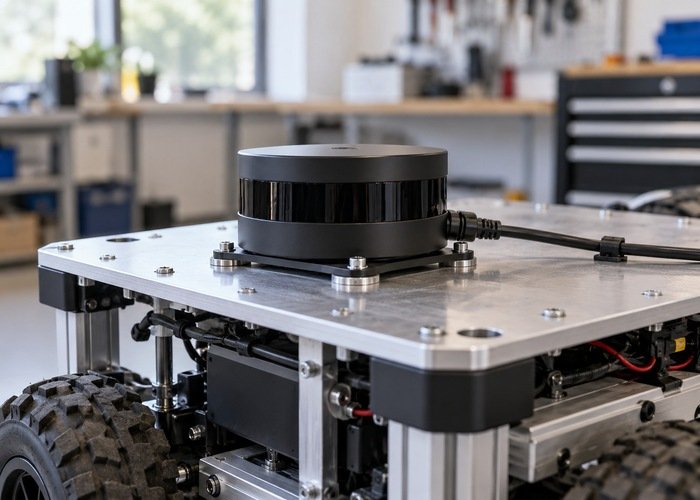
Define directions at the sensor before using a world frame
The LaserScan contract measures angles around positive z, with zero along positive x. Its header identifies the sensor frame and the acquisition time of the first ray. Start with this local representation rather than a map view that combines scan geometry with several transforms.
Locate the sensor manufacturer’s physical reference and compare it with the installed frame. The common body axes in REP 103 use a right-handed convention. Document any deliberate difference between the sensor’s native coordinates, the driver’s output coordinates and the robot’s base coordinates. A drawing with an unlabeled forward arrow is insufficient evidence.
Use several distinguishable stationary objects, placed within the sensor’s documented measurement conditions and test procedure. Avoid a symmetric corridor as the only reference: its outline can conceal a reversal or half-turn. Record which return belongs to which object, including uncertainty about object edges or occlusion. Keep the robot and target positions unchanged during the initial comparison.
Pair each array index with its declared bearing
For the ordinary uniformly sampled message contract, inspect the relationship theta_i = angle_min + i * angle_increment. Retain the array length, first and last declared directions and increment together. The count and angular span should be mutually coherent within the producer’s numerical conventions. Do not infer correctness from angle_max alone while ignoring the actual array order.
The inspected laser_geometry projection implementation forms Cartesian directions from that index-and-angle relationship. This explains why changing the array without matching metadata can produce a geometrically wrong cloud even if every range number remains unchanged. Confirm the installed consumer’s actual assumptions and filtering behavior.
Build a small worksheet for identifiable returns: original index, range, calculated bearing, associated target and expected physical direction. Exclude invalid returns according to the message and producer contract. If a filter removes samples, determine whether it preserves their positions in the array or publishes a new angular window with new metadata.
Keep range validity separate from directional interpretation. A missing or out-of-range return does not identify a left-right reversal. Preserve the original recording before selecting representative samples, following the sensor recording workflow. That allows a reviewer to inspect both the selected examples and the surrounding scan.
Trace driver inversion, reordering and crop options
Read the effective driver parameters and the code path for the exact installed model and scan mode. Words such as inverted, reversed or clockwise can describe different stages in different drivers. Establish whether an option changes angle values, array ordering, mounting interpretation or more than one of these. Do not transfer an option’s meaning between unrelated packages.
For example, the inspected Slamtec ROS 2 driver source contains explicit angle construction and conditional range-array reversal in its publishing routine. It is an implementation example, not evidence that another scanner needs the same setting. Compare the deployed branch and resulting messages with the retained targets.
Check crop and sector-removal stages after the driver too. A custom republisher may retain only part of a scan, reverse data for display, or relabel a frame. Record the incoming and outgoing metadata at every such boundary. A valid original driver message does not prove a later republished message preserves the same index-to-bearing contract.
A physical mount rotation is a separate issue. The mobile platform frame conventions distinguish a rigid robot frame from world frames. If the scan is correct in its own sensor frame but wrong after transformation, investigate the mounting transform instead of rewriting its ranges. The installation calibration workflow helps preserve measured geometry independently.
Keep ray timing coherent with geometry
Array order has a timing consequence as well as an angular consequence. Determine what the producer means by the first ray and by time_increment after any reordering. Do not apply a negative-time workaround copied from a historical issue report without checking the installed producer and every affected consumer. A static display cannot validate motion compensation.
Record the original header time, per-ray timing convention and scan interval. After the stationary geometry check passes, use an approved controlled motion test to inspect temporal behavior separately. The sensor clock-check guide addresses time domains; a correct clock alone does not establish that timestamps still correspond to the reordered rays.
Likewise, an unavailable transform at a ray’s time is different from an incorrectly assigned angle. Use the TF extrapolation diagnostic when time coverage fails. Keep the geometry, mounting and timing findings separate so one apparently improved visualization cannot obscure a remaining contract error.
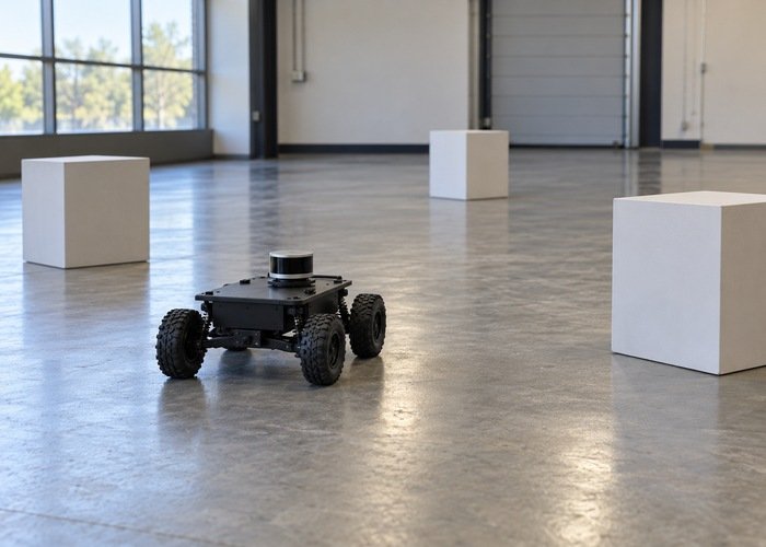
Compare one boundary at a time
| Observation | Inspect next | Retain |
|---|---|---|
| Wrong target directions in sensor frame | Angle/index pairing and producer options | Original message and target worksheet |
| Correct sensor scan, wrong base-frame view | Measured mount transform | Frame chain and physical installation reference |
| Shift begins after crop or republish | New angular window and sample ordering | Input/output messages and configuration |
| Static geometry works, moving scene distorts | First-ray timing and transform coverage | Timing contract and controlled motion segment |
| Only one application appears incorrect | That consumer’s assumptions and fixed frame | Exact consumer revision and settings |
Change a single supported setting or correction, then repeat the same target comparison with the same visualization frame. Confirm that a downstream consumer receives the intended message rather than a similarly named old topic. Define acceptance criteria from the application’s geometric and timing requirements before judging the result. A recognizable room outline alone is a weak acceptance test.
When an auxiliary array such as intensities is populated, verify that any supported reordering keeps it associated with the same rays. A correction that moves ranges but leaves related sample information in the original order creates another inconsistency. Keep the original and transformed message side by side, and document which fields a republisher preserves, recomputes or omits. This gives later consumers an auditable contract rather than an unexplained display-only adjustment.
Common integration questions
Can I reverse ranges to repair a mirrored scan?
Only as part of a supported transformation that preserves the angle and timing contracts. Reversing an array independently can repair one screenshot while making other consumers incorrect.
Does a rotated scan always mean the mount transform is wrong?
No. Establish the raw sensor-frame geometry first. Then inspect the transformation to the base or world frame. The location where the discrepancy first appears determines the next check.
What belongs in an actionable support request?
Include a short original scan recording, target directions, the index worksheet, effective driver options and exact versions. The reproducible support bundle guide helps package them. State whether the first mismatch occurs in the producer, a republisher, the transform chain or one consumer.