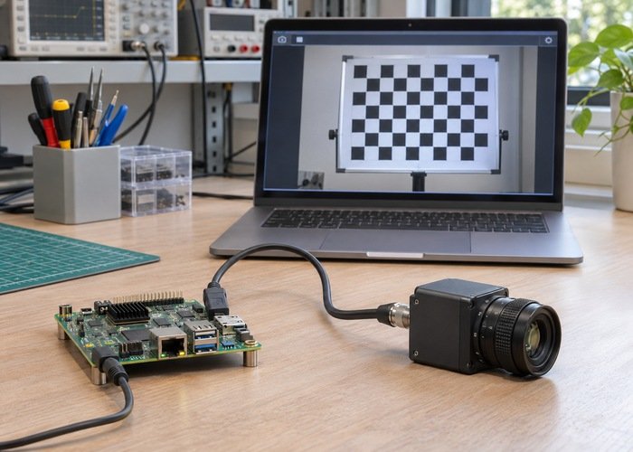
If a Jetson camera delivers fewer frames than requested after selecting a sensor mode, compare the selected mode, effective exposure controls and captured frame intervals before changing the hardware. A requested frame rate describes an application setting. It does not establish which sensor mode was loaded or the rate at which completed frames actually reached the consumer.
Preserve the camera model, driver revision, Jetson Linux release, capture path and exact startup command. This workflow uses the official r36.3 documentation as a reference. Match its details to the installed release rather than mixing commands from unrelated platform versions. A camera connected to Jetson does not automatically support every NVIDIA-specific control.
The camera software architecture guide distinguishes capture approaches. Establish whether the application uses Argus, a GStreamer path or direct V4L2. The multi-camera CSI budget guide addresses a different question: whether the combined deployment fits its transport and processing resources.

Separate the requested setting from the selected mode
List the requested resolution, pixel format and frame rate, then record the mode the running capture stack actually selected. Preserve the available mode list and the startup messages that identify the choice. A familiar resolution can exist in several modes with different timing, bit depth or readout arrangements.
Do not infer the active mode from a configuration filename. Compare the effective startup arguments and the driver’s accepted controls. Record the source of each value: application request, driver readback, capture metadata or independent timing measurement. These observations answer different questions and should remain separate in the investigation worksheet.
The r36.3 Argus NvRaw reference provides a supported context for inspecting sensor information where the tool and camera path apply. It is not a general replacement for every USB, virtual or third-party camera interface. Keep unsupported capabilities explicitly marked rather than inventing a readback.
Inspect mode selection and control ordering
The NVIDIA V4L2 Argus control reference documents camera-mode and frame-rate interactions for that interface. Control ordering can matter. Compare the actual sequence used by the application with the applicable reference instead of assuming that two sequences producing the same final text settings are equivalent.
Save the accepted controls after startup and after any mode change. Include return codes and warnings, because an application may continue after a control request is rejected. An unchanged output rate can therefore indicate a rejected request, an overwritten request or a different active capture path.
Test one controlled change at a time. Start with a known supported mode and preserve its baseline. Change the intended mode or exposure setting, then restart using the documented procedure where required. Combining a new driver, different cable, new mode and different consumer in one test makes it difficult to identify the boundary that changed.
| Record | What it establishes | What it cannot establish alone |
|---|---|---|
| Requested frame rate | Application intent | Actual sensor or delivery rate |
| Selected mode | Chosen timing and format context | Successful downstream processing |
| Exposure readback | Reported capture setting | All image-quality or latency behavior |
| Frame timestamps | Intervals at an identified boundary | Intervals at every other boundary |
| Consumer throughput | Completed application work | Sensor acquisition rate |
Check exposure against the mode’s timing
Record the exposure policy and the effective exposure range for the selected mode. Long exposure requests and automatic control behavior can interact with the available frame timing. Establish what the installed driver supports before expecting a particular requested rate to coexist with every exposure value.
The sensor-driver programming guide describes mode-specific timing and exposure controls. Its example values belong to example hardware and configuration. Do not copy those values into another sensor’s device tree or treat them as a specification for a product that has not been identified.
Keep exposure, gain and illumination observations in the same record. A darker image after limiting exposure does not by itself establish that the capture path is repaired. Use a stable scene, preserve image-quality requirements and evaluate the resulting frames alongside the measured intervals.
For a combined sensor system, review the camera optical-frame checks independently. A correct frame rate does not establish correct coordinate alignment, and changing a transform cannot repair rejected camera controls.
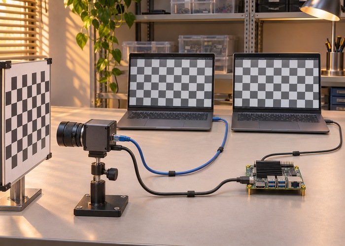
Measure at identified boundaries
Collect a bounded sequence of frame timestamps and identify their meaning. Separate sensor acquisition timestamps, driver delivery times and application completion times. Use the clock definition associated with each observation. Comparing different clock domains without accounting for their relationship can produce misleading latency or frame-interval conclusions.
The capture metadata reference identifies information reported by the applicable NVIDIA interface. Record which fields are available in the actual path. Do not replace absent metadata with an assumed sensor timestamp and then report that assumption as a measurement.
Count frames arriving at the capture boundary separately from frames processed or displayed. A visualization can intentionally display fewer frames than it receives. Likewise, a slow consumer can retain older buffers and make the visible stream appear irregular even when upstream acquisition remains steady.
Use the callback execution diagnostic when the problem appears only with multiple perception workloads. Preserve the single-camera baseline before attributing the difference to exposure. Resource contention and sensor timing are competing hypotheses that need separate observations.
Repeat a small, reproducible comparison
Choose a short test matrix: the supported baseline mode, the requested alternative mode, a documented exposure change, and the normal application workload. For each row, save requested settings, accepted controls, observed mode, frame count and timestamp intervals. Define the acceptance criteria before comparing results.
Include a normal restart with the saved configuration. A successful interactive session does not prove that a service or container loads the same settings. Preserve the effective environment and the actual configuration path used by the running process.
When camera data is paired with LiDAR, the synchronizer diagnostic helps distinguish irregular acquisition from a message-pairing policy that produces fewer callbacks. Count source messages and paired outputs separately rather than assigning every low paired rate to the camera.
Prepare a reproducible support bundle containing mode information, platform versions, settings, metadata and a bounded timestamp sample. State whether the failure is unsupported mode selection, rejected controls, changed acquisition timing or downstream processing. That distinction makes the next engineering action reviewable.
Keep startup transients separate from the steady observation window. Record the number of frames excluded and the reason for excluding them. Otherwise a different warm-up period can look like a frame-rate change. Preserve the raw timestamp sample so another engineer can repeat the calculation without relying on a rounded average.
Also record where the counter runs. Counting a display refresh, a ROS subscription callback and a completed capture buffer measures different boundaries. Use matching windows and identified clocks when comparing two paths. If the result changes only at the final consumer, investigate that consumer before modifying the camera timing configuration.
Frequently asked questions
Does requesting a rate guarantee it?
No. Confirm the selected mode, accepted controls and measured intervals at the boundary that matters to the application.
Should I copy timing values from an example driver?
No. Example values describe specific hardware. Use the identified sensor’s supported modes and the matching platform documentation.
Can a low paired LiDAR-camera rate prove the camera is slow?
No. Pairing policy, timestamps and downstream load can reduce paired output. Measure each source independently before interpreting the combined result.