LiDAR profiling reference artifacts should answer a practical question: can a team reproduce the measurement or navigation result after the scene, operator or operating day changes? The quick answer is to define the decision, establish a stable reference, test the difficult geometry, and save enough evidence to distinguish sensor limits from mounting, timing and processing errors.
Begin with the measured intent behind this guide and the closest application page, lidar profiling field context. Teams comparing hardware can also review the LiDAR sensor catalog, but the useful shortlist starts with targets, range, field of view, motion, interface and a written failure case—not a feature count.
This guide turns those requirements into a field workflow. It covers setup choices, common traps, acceptance evidence, maintenance and handoff, with a checklist that purchasing and engineering can use together.

Design The Artifact Around The Measurand
LiDAR profiling reference artifacts becomes useful only when the team connects the measurement to a physical decision. In design the artifact around the measurand, document the target, distance, mounting position, motion, surface condition and output that another system or operator will consume. A clean point cloud is encouraging, but the acceptance evidence is the repeatable result under the same written conditions. The NOAA LiDAR overview provides neutral technical context for defining the test.
Start with the difficult case, not the comfortable demonstration. Mark the steep face, crossing cart, hidden edge, reflective part, dusty window or timing transition that can change the outcome. Run an easy baseline first, add one difficulty at a time, and preserve raw data with the configuration. This makes a failure diagnosable instead of mysterious. Relate that evidence to LiDAR sensor catalog before finalizing the project request.
Mounting deserves its own record. Photograph the bracket, measure the sensor pose, note cable strain and protective hardware, and record anything that can move after service. Small physical changes can look like software drift. A signed mounting sketch and a short restart test often prevent days of argument later.
Treat software settings as controlled test equipment. Save frame names, timestamps, filters, thresholds, firmware, processing versions and coordinate choices beside the raw capture. If an operator cannot recreate the result after a reboot, the setup is not ready for routine work regardless of how convincing the first visualization looked.
Choose Datums Steps And Surface Finishes
Start with the difficult case, not the comfortable demonstration. Mark the steep face, crossing cart, hidden edge, reflective part, dusty window or timing transition that can change the outcome. Run an easy baseline first, add one difficulty at a time, and preserve raw data with the configuration. This makes a failure diagnosable instead of mysterious. The USGS LiDAR base specification provides neutral technical context for defining the test.
Mounting deserves its own record. Photograph the bracket, measure the sensor pose, note cable strain and protective hardware, and record anything that can move after service. Small physical changes can look like software drift. A signed mounting sketch and a short restart test often prevent days of argument later. Relate that evidence to robotics LiDAR solutions before finalizing the project request.
Treat software settings as controlled test equipment. Save frame names, timestamps, filters, thresholds, firmware, processing versions and coordinate choices beside the raw capture. If an operator cannot recreate the result after a reboot, the setup is not ready for routine work regardless of how convincing the first visualization looked.
Build a pass condition that says what must be detected or measured, where it must happen and how often it must repeat. Avoid a single percentage without context. Keep the reference method, coverage, sample count and excluded conditions visible so that purchasing, engineering and operations are discussing the same evidence.
Field Decision Table
| Decision | What to record | Pass evidence |
|---|---|---|
| Geometry | Targets, range, angles, hidden surfaces | Coverage images and raw capture |
| Timing | Rate, timestamps, speed, latency | Logs from the fastest normal cycle |
| Environment | Light, dust, weather, vibration | Repeated hard-condition run |
| Handoff | Versions, mounts, thresholds, owner | Second operator reproduces result |
Control Handling Storage And Temperature
Mounting deserves its own record. Photograph the bracket, measure the sensor pose, note cable strain and protective hardware, and record anything that can move after service. Small physical changes can look like software drift. A signed mounting sketch and a short restart test often prevent days of argument later. The NIST laser scanner ranging tests provides neutral technical context for defining the test.
Treat software settings as controlled test equipment. Save frame names, timestamps, filters, thresholds, firmware, processing versions and coordinate choices beside the raw capture. If an operator cannot recreate the result after a reboot, the setup is not ready for routine work regardless of how convincing the first visualization looked. Relate that evidence to industrial automation LiDAR before finalizing the project request.
Build a pass condition that says what must be detected or measured, where it must happen and how often it must repeat. Avoid a single percentage without context. Keep the reference method, coverage, sample count and excluded conditions visible so that purchasing, engineering and operations are discussing the same evidence.
The handoff should include an ordinary maintenance check. Dust, window contamination, vibration, thermal change, pallet movement and lighting transitions are normal field conditions. Decide who inspects the sensor, how a degraded result is recognized, when a reference run is required and what record closes the issue.
The video below is a visual research reference for real sensor capture and integration. Use it to understand the workflow, then validate every important condition with the project’s own targets, route, line speed and mounting constraints.
Run Beginning Middle And End-Shift Checks
Treat software settings as controlled test equipment. Save frame names, timestamps, filters, thresholds, firmware, processing versions and coordinate choices beside the raw capture. If an operator cannot recreate the result after a reboot, the setup is not ready for routine work regardless of how convincing the first visualization looked. The ROS 2 LaserScan documentation provides neutral technical context for defining the test.
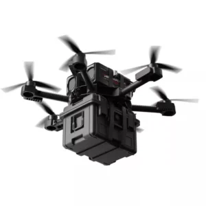
Build a pass condition that says what must be detected or measured, where it must happen and how often it must repeat. Avoid a single percentage without context. Keep the reference method, coverage, sample count and excluded conditions visible so that purchasing, engineering and operations are discussing the same evidence. Relate that evidence to drone LiDAR systems before finalizing the project request.
The handoff should include an ordinary maintenance check. Dust, window contamination, vibration, thermal change, pallet movement and lighting transitions are normal field conditions. Decide who inspects the sensor, how a degraded result is recognized, when a reference run is required and what record closes the issue.
LiDAR profiling reference artifacts becomes useful only when the team connects the measurement to a physical decision. In run beginning middle and end-shift checks, document the target, distance, mounting position, motion, surface condition and output that another system or operator will consume. A clean point cloud is encouraging, but the acceptance evidence is the repeatable result under the same written conditions.
Use Trend Limits To Trigger Recovery
Build a pass condition that says what must be detected or measured, where it must happen and how often it must repeat. Avoid a single percentage without context. Keep the reference method, coverage, sample count and excluded conditions visible so that purchasing, engineering and operations are discussing the same evidence. The ROS 2 PointCloud2 documentation provides neutral technical context for defining the test.
The handoff should include an ordinary maintenance check. Dust, window contamination, vibration, thermal change, pallet movement and lighting transitions are normal field conditions. Decide who inspects the sensor, how a degraded result is recognized, when a reference run is required and what record closes the issue. Relate that evidence to LiDAR application solutions before finalizing the project request.
LiDAR profiling reference artifacts becomes useful only when the team connects the measurement to a physical decision. In use trend limits to trigger recovery, document the target, distance, mounting position, motion, surface condition and output that another system or operator will consume. A clean point cloud is encouraging, but the acceptance evidence is the repeatable result under the same written conditions.
Start with the difficult case, not the comfortable demonstration. Mark the steep face, crossing cart, hidden edge, reflective part, dusty window or timing transition that can change the outcome. Run an easy baseline first, add one difficulty at a time, and preserve raw data with the configuration. This makes a failure diagnosable instead of mysterious.
A Practical Acceptance-Day Walkthrough
LiDAR profiling reference artifacts becomes useful only when the team connects the measurement to a physical decision. In acceptance-day walkthrough, document the target, distance, mounting position, motion, surface condition and output that another system or operator will consume. A clean point cloud is encouraging, but the acceptance evidence is the repeatable result under the same written conditions. Compare the record with Nav2 sensor setup where the source applies.
Start with the difficult case, not the comfortable demonstration. Mark the steep face, crossing cart, hidden edge, reflective part, dusty window or timing transition that can change the outcome. Run an easy baseline first, add one difficulty at a time, and preserve raw data with the configuration. This makes a failure diagnosable instead of mysterious. The next hardware or integration discussion can start from request a project recommendation.
Mounting deserves its own record. Photograph the bracket, measure the sensor pose, note cable strain and protective hardware, and record anything that can move after service. Small physical changes can look like software drift. A signed mounting sketch and a short restart test often prevent days of argument later. Compare the record with Nav2 collision monitor where the source applies.
Treat software settings as controlled test equipment. Save frame names, timestamps, filters, thresholds, firmware, processing versions and coordinate choices beside the raw capture. If an operator cannot recreate the result after a reboot, the setup is not ready for routine work regardless of how convincing the first visualization looked. The next hardware or integration discussion can start from LiDAR application resources.
Build a pass condition that says what must be detected or measured, where it must happen and how often it must repeat. Avoid a single percentage without context. Keep the reference method, coverage, sample count and excluded conditions visible so that purchasing, engineering and operations are discussing the same evidence. Compare the record with OSHA robot system safety guidance where the source applies.
The handoff should include an ordinary maintenance check. Dust, window contamination, vibration, thermal change, pallet movement and lighting transitions are normal field conditions. Decide who inspects the sensor, how a degraded result is recognized, when a reference run is required and what record closes the issue. The next hardware or integration discussion can start from LiDAR sensor catalog.
LiDAR profiling reference artifacts becomes useful only when the team connects the measurement to a physical decision. In acceptance-day walkthrough, document the target, distance, mounting position, motion, surface condition and output that another system or operator will consume. A clean point cloud is encouraging, but the acceptance evidence is the repeatable result under the same written conditions. Compare the record with FDA laser product guidance where the source applies.

Buyer And Engineer Checklist
- Write the real target, distance, speed and mounting envelope.
- Provide sample data and required output formats.
- Name the difficult surfaces, occlusions and environmental transitions.
- Define timing, coordinate frames and synchronization responsibility.
- Agree on reference measurements and repeatability checks.
- Preserve firmware, configuration, raw logs and mounting photos.
- Confirm maintenance access, contamination checks and change control.
- Run the acceptance route after reboot with a second operator.
Build a pass condition that says what must be detected or measured, where it must happen and how often it must repeat. Avoid a single percentage without context. Keep the reference method, coverage, sample count and excluded conditions visible so that purchasing, engineering and operations are discussing the same evidence. The review should end with a clear accept, revise or reject decision and the evidence behind it.
Start with the difficult case, not the comfortable demonstration. Mark the steep face, crossing cart, hidden edge, reflective part, dusty window or timing transition that can change the outcome. Run an easy baseline first, add one difficulty at a time, and preserve raw data with the configuration. This makes a failure diagnosable instead of mysterious. The review should end with a clear accept, revise or reject decision and the evidence behind it.
Build a pass condition that says what must be detected or measured, where it must happen and how often it must repeat. Avoid a single percentage without context. Keep the reference method, coverage, sample count and excluded conditions visible so that purchasing, engineering and operations are discussing the same evidence. The review should end with a clear accept, revise or reject decision and the evidence behind it.
Start with the difficult case, not the comfortable demonstration. Mark the steep face, crossing cart, hidden edge, reflective part, dusty window or timing transition that can change the outcome. Run an easy baseline first, add one difficulty at a time, and preserve raw data with the configuration. This makes a failure diagnosable instead of mysterious. The review should end with a clear accept, revise or reject decision and the evidence behind it.
Build a pass condition that says what must be detected or measured, where it must happen and how often it must repeat. Avoid a single percentage without context. Keep the reference method, coverage, sample count and excluded conditions visible so that purchasing, engineering and operations are discussing the same evidence. The review should end with a clear accept, revise or reject decision and the evidence behind it.
Start with the difficult case, not the comfortable demonstration. Mark the steep face, crossing cart, hidden edge, reflective part, dusty window or timing transition that can change the outcome. Run an easy baseline first, add one difficulty at a time, and preserve raw data with the configuration. This makes a failure diagnosable instead of mysterious. The review should end with a clear accept, revise or reject decision and the evidence behind it.
Conclusion
LiDAR profiling reference artifacts is reliable when the team controls geometry, reference, timing, processing and the acceptance record as one system. A sensor specification can narrow the options, but only a repeatable field test shows whether the complete setup fits the work. Finish with an evidence package that operations can rerun, then use the result to select, mount and maintain the sensor with confidence.
Frequently Asked Questions
What should be tested first?
Test the hardest normal target or route after recording a clean baseline. This reveals whether the design has real operating margin.
How many repeat runs are enough?
Use enough runs to cover ordinary variability and a second operator. The exact number depends on risk, but one successful demonstration is not acceptance.
Should processed output or raw data be kept?
Keep both. Processed output proves what the application used; raw data allows later diagnosis when settings or algorithms change.
How should mounting changes be handled?
Treat any pose, bracket or protection change as controlled. Record it and rerun the relevant reference and hard-case tests.
Can a supplier specification replace field validation?
No. Specifications guide selection, while field validation checks the complete sensor, mount, environment, timing and software chain.
What belongs in the final handoff?
Include requirements, mounting photos, configuration, versions, raw logs, reference results, failures, maintenance steps and named owners.