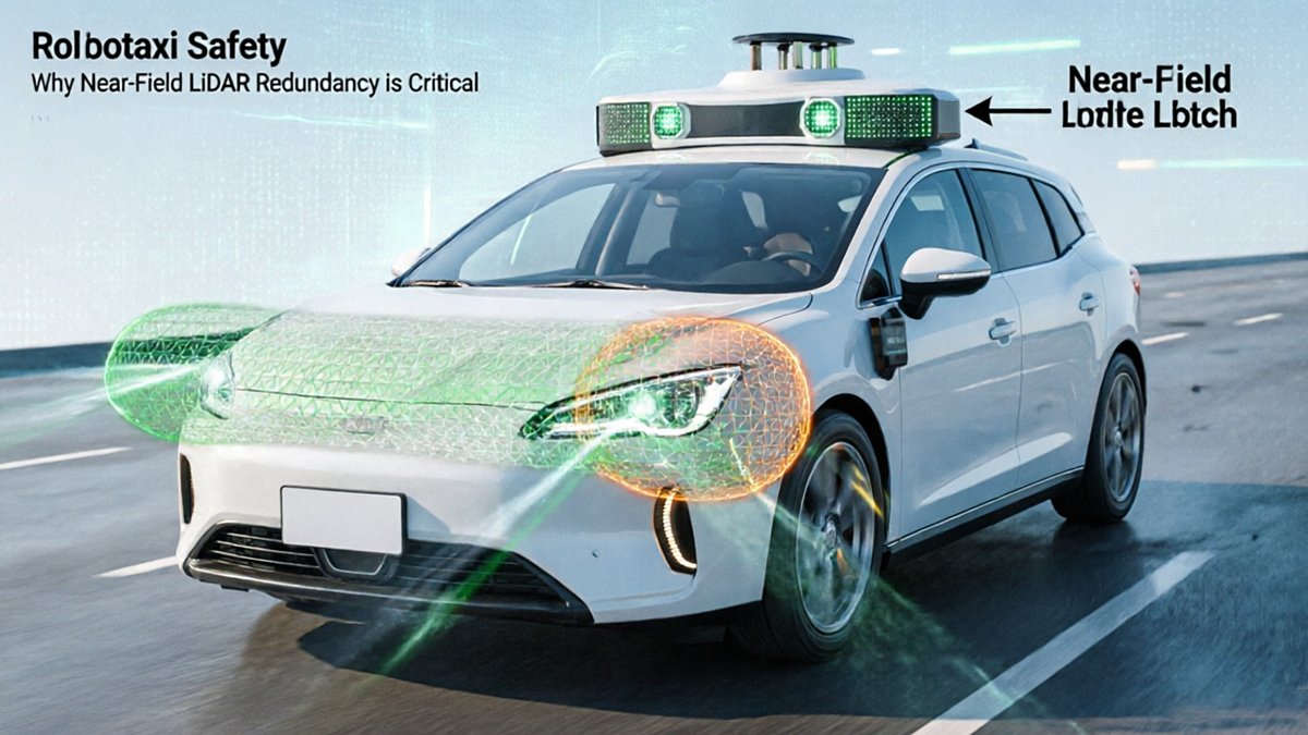
Robotaxi LiDAR sensorssors mounted on rooftops are remarkably capable at long range — and surprisingly blind right at their feet.
This isn’t a minor calibration quirk. It’s a structural limitation baked into the physics of elevated, forward-looking sensor arrays. Long-range LiDAR units require a minimum detection distance to resolve returns accurately. Below that threshold — typically within 3 to 5 meters of the vehicle body — the beam angles grow too shallow to illuminate low-profile objects reliably. The result is a persistent blind zone hugging the vehicle’s perimeter at ground level.
The Near-Field Blind Spot: The unmonitored zone directly surrounding a robotaxi’s chassis — typically 0 to 5 meters from the body — where roof-mounted long-range sensors cannot achieve reliable ground-plane detection due to angular geometry constraints.
Low-profile hazards expose the stakes immediately. Curbs at odd angles, a child crouching between parked cars, a small animal darting into a crosswalk — none of these fit neatly into a sensor’s sweet spot when that sensor is designed to see hundreds of meters ahead. As SAE International notes, relying solely on long-range sensors creates a “donut” of invisibility around the vehicle base — a gap that urban environments fill with precisely the kind of unpredictable, low-height obstacles that matter most.
Hybrid sensor configurations are the practical answer. Combining high-performance long-range units — like those profiled in our deep-dive on 360° automotive LiDAR — with dedicated near-field sensors creates overlapping coverage zones that eliminate the blind spot entirely. This layered architecture isn’t elegant by accident; it’s an engineering necessity. Understanding why regulators increasingly treat redundancy as non-negotiable requires a closer look at the safety frameworks shaping L4 approval.
Why Redundancy is the Regulatory Bedrock of L4 Autonomy
Removing the human driver from a robotaxi isn’t a software milestone — it’s a regulatory threshold that demands airtight, layered perception with zero single points of failure.
“Redundancy in the perception stack is not a luxury for Robotaxis; it is a regulatory and safety requirement for removing the human driver.” — McKinsey & Company
The shift from “nice-to-have” to “non-negotiable” happened the moment regulators began evaluating L4 driverless permits. Without a human ready to grab the wheel, every gap in sensor coverage — including near-field blind spot detection around the vehicle’s immediate perimeter — becomes a potential liability that can delay or revoke operational approval.
The Minimal Risk Maneuver (MRM) is central to understanding why. An MRM is the vehicle’s fallback behavior when a sensor degrades or fails: safely pulling over, halting in lane, or navigating to a safe zone without human input. Executing an MRM correctly requires that the remaining sensors still deliver enough situational awareness to avoid hazards. If a single LiDAR unit fails and takes out a critical coverage zone, the system may not have enough data to maneuver safely — a scenario regulators explicitly test for.
Perception stack depth is therefore the architectural argument for redundancy. Overlapping sensor fields create a failsafe mesh: if one node drops out, adjacent sensors absorb the gap. This is why understanding how sensor technology scales for L4 use cases matters — the underlying detection physics determine how gracefully a stack degrades under partial failure.
Regulatory bodies tie approval timelines directly to demonstrated redundancy. Operators that can show validated overlapping coverage and MRM simulation data move through permitting faster. Those that can’t face extended review cycles and operational restrictions — a costly outcome in a market where every mile of driverless operation matters.
That architecture of overlapping coverage is precisely where hybrid sensor configurations come in.
The Hybrid Configuration: Pairing Long-Range and Wide-Angle Sensors
A robust L4 perception stack redundancy strategy isn’t built on a single sensor — it’s engineered through deliberate hardware pairing that eliminates coverage gaps at every distance band.
In practice, a well-designed robotaxi sensor suite combines two complementary sensor classes:
- Primary long-range LiDAR (128-channel): Mounted on the roof, high-channel-count units generate dense point clouds at distances exceeding 200 meters, handling highway-speed hazard detection and intersection mapping with precision.
- Wide-angle near-field LiDAR: Lower-mounted sensors with a vertical Field of View (FoV) exceeding 75 degrees — as noted by [SAE International](https://www.sae.org) — capture low-profile objects, cyclists, and pedestrians in the critical near-field zone that rooftop units miss.
- Bumper and fender-integrated units: Placement at bumper height addresses the geometric blind spots created by rooftop sensor angles, covering the “blind spot” zone discussed earlier from a physical vantage point that changes detection geometry entirely.
- Ultrasonic and radar supplements: Short-range radar fills remaining gaps in adverse weather conditions, adding a passive layer where optical sensors degrade.
Placement matters as much as specification. Roof-mounted sensors dominate long-range performance but suffer steep vertical angle limitations below roughly 10 meters. Fender-level integration corrects this by bringing wide-FoV sensors physically closer to curb height — exactly where pedestrian feet, wheel chocks, and debris live.
The real engineering tension lies in balancing data density with processing overhead. A 128-channel primary unit paired with multiple wide-angle sensors generates point cloud volumes that stress real-time compute pipelines. One practical approach is selective downsampling in low-priority zones while preserving full resolution in active detection regions. Understanding the underlying sensor architecture driving these tradeoffs is essential for building systems that perform reliably — not just on spec sheets.
That hardware-level reliability question leads directly to a deeper debate: whether LiDAR is even necessary when cameras have become so capable.
LiDAR vs. Camera Systems: The Physics of 24/7 Reliability
Cameras see light; LiDAR creates it — and that fundamental difference in physics defines which sensor technology earns the right to operate without a safety driver.
Active vs. passive sensing is the core distinction. A camera is a passive device — it captures ambient photons reflected off the environment. When that ambient light fails, so does the camera. Tunnel exits, oncoming high-beams, and pre-dawn street runs all represent conditions where image quality degrades unpredictably. LiDAR, by contrast, fires its own laser pulses and measures the return time to build a precise 3D point cloud — entirely independent of the sun, streetlights, or oncoming headlights.
In practice, this difference becomes operationally critical:
- High-glare scenarios (tunnel exits, low-angle sun): Camera exposure algorithms struggle with sudden luminance shifts; LiDAR point clouds remain stable because the sensor controls its own light source
- Low-light environments (overnight operations, covered parking): Camera noise and reduced contrast degrade object classification; LiDAR range and accuracy are largely unaffected
- Adverse reflective surfaces (wet asphalt, chrome bumpers): Camera-based depth estimation collapses; LiDAR time-of-flight calculations remain accurate
Bold callout: According to IEEE, LiDAR sensorssor fusion reduces perception error rates by up to 30% compared to camera-only systems in low-light and high-glare conditions.
The “vision-only” argument often points to cost and scale. Those are legitimate engineering trade-offs. However, the data-driven counterpoint is straightforward: a 30% reduction in perception errors at the edge cases — precisely the scenarios most likely to produce collisions — isn’t a marginal improvement; it’s a safety-critical one. Understanding how different LiDAR ranging methods perform under these conditions adds another layer to the hardware selection decision.
The next challenge is where to physically place these sensors — particularly in the vehicle’s most vulnerable blind-spot zones, where form factor and durability matter as much as raw performance.
The Rise of Solid-State LiDAR for Blind-Spot Coverage
Solid-state LiDAR for robotics is rapidly becoming the default choice for near-field coverage precisely because it solves the durability and packaging problems that mechanical scanners cannot.
The core advantage is mechanical simplicity: no rotating parts means no failure modes triggered by road vibration, thermal cycling, or repeated impact — all conditions that bumpers and fenders endure constantly.
Durability in high-vibration zones. Traditional spinning LiDAR units tolerate roof-mount placement well, but they’re poorly suited to bumper-level integration where shock loads are far higher. Solid-state and flash LiDAR technologies are increasingly preferred for blind-spot coverage due to their high reliability and lack of moving parts, according to Gartner. That structural resilience makes them the only realistic option for embedding sensors directly into bodywork.
Embedding into vehicle architecture. Form factor matters enormously at fleet scale. Solid-state units are compact enough to disappear into:
- Front and rear bumpers for short-range object detection
- Rocker panels and lower pillars for pedestrian-level coverage
- Side mirror housings for lateral gap monitoring
This integration preserves aerodynamics, reduces vandalism risk, and keeps the sensor’s field of view close to the ground plane where near-field threats actually appear.
Flash vs. mechanical scanning for precision. Unlike mechanical scanners that reconstruct a scene line-by-line over time, flash LiDAR captures the scene as a single synchronized snapshot — a critical advantage when a pedestrian is moving at crosswalk speed within three meters of the vehicle.
Cost at fleet scale. Solid-state units carry a significantly lower per-unit cost and longer mean time between failures than their mechanical counterparts, making the economics of equipping an entire robotaxi fleet far more tractable.
To see these principles in action — and understand how point cloud density translates into real-world blind-spot elimination — the next section breaks down a technical visualization worth examining closely.
Integrating a YouTube Technical Deep Dive
A point cloud visualization makes abstract sensor theory concrete — seeing 128 channels render a live urban scene in real-time changes how engineers think about coverage gaps.
Point cloud density tells the real story. In the video above, pay close attention to how a 128-channel unit saturates the near-field with returns — pedestrians, curb edges, and low-profile obstacles all resolve as distinct clusters within meters of the vehicle. According to the Journal of Unmanned Vehicle Systems, LiDAR provides its own light source, maintaining consistent point cloud density regardless of ambient conditions. That consistency is visible in the demo: the cloud doesn’t thin out under simulated low-light conditions the way a camera feed degrades.
Sensor fusion overlap is the second element worth analyzing closely. The simulation sequences a wide-angle LiDAR configuration alongside a primary roof-mounted unit, and the overlap zone — typically the 0–15 meter radius around the vehicle — is where redundancy actually earns its value. Watch how the secondary sensor fills the “shadow” zones that appear when a pedestrian steps directly beside the chassis. Without that coverage handoff, the perception stack registers a momentary blind spot. High-channel-count platforms designed for L4+ demonstrate precisely this fusion architecture in production hardware.
Transition analysis — how cleanly the system stitches returns from both sensors into a unified model — is the third thing to watch. Seam artifacts or latency mismatches in the fused cloud indicate integration challenges that no amount of algorithmic tuning fully compensates for. Clean fusion, by contrast, produces a seamless 360-degree shell around the vehicle.
Getting this architecture right on paper is one challenge; sourcing the hardware to build and iterate on it efficiently is another problem entirely.
Streamlining the Procurement Pipeline for Autonomous R&D
Getting the sensor stack right technically is only half the battle — sourcing automotive-grade hardware reliably, at speed, is what separates teams that ship from teams that stall.
Factory-direct procurement is the single biggest lever R&D teams can pull to protect both budget and timeline. The challenge is that automotive-grade LiDAR sensorssors have historically moved through multi-tier distribution chains, inflating costs and stretching lead times that early-stage robotaxi programs simply can’t afford. Every intermediary layer adds margin, obscures firmware versioning, and creates accountability gaps when field issues arise.
A growing alternative is the “supermarket” sourcing model — a direct-to-engineer catalog approach where teams can compare sensor architectures side by side, configure specifications, and place orders without navigating distributor negotiations. For startups operating on constrained R&D budgets, this model reduces procurement friction dramatically, compressing weeks of vendor back-and-forth into days.
24-hour technical support is a non-negotiable for engineering teams running iterative hardware-in-the-loop testing. Sensor integration issues don’t observe business hours — a calibration anomaly discovered at 11 PM can block an entire sprint. Access to factory engineers around the clock means faster root-cause resolution, fewer lost testing cycles, and more confidence ahead of fleet deployment.
LidarStar addresses each of these pain points directly, offering factory pricing on automotive-grade LiDAR sensorssors, global shipping logistics, and 24-hour technical support — structured specifically for engineering teams that need hardware velocity without sacrificing component quality.
Eliminating intermediaries also preserves flexibility. When a perception architecture evolves mid-program, direct supplier relationships allow rapid specification changes rather than re-qualifying through a distribution chain.
With the procurement pipeline in focus, it’s worth crystallizing exactly which technical and operational principles should guide every robotaxi sensor decision — which the next section addresses directly.
The Bottom Line: Key Takeaways for Robotaxi Sensor Selection
Robotaxi safety is ultimately a sensor architecture problem — and the decisions made at the design stage determine whether a vehicle can reliably protect passengers, pedestrians, and cyclists in the real world.
With procurement pipelines now more streamlined than ever, engineering teams have fewer excuses to cut corners on near-field coverage. Here are the core principles that should guide every robotaxi sensor selection decision:
- Eliminate the ‘blind spot’ with 360-degree redundancy. A single roof-mounted LiDAR leaves a critical blind zone around the vehicle base. Distributing near-field sensors at multiple mounting heights ensures no gap survives into production deployment.
- Prioritize wide-FoV solid-state sensors (>75° vertical) for urban near-field gaps. Tight intersections, cyclists brushing the curb, and pedestrians stepping off raised platforms all demand downward-angled coverage that long-range units simply can’t provide. Understanding how predictive perception handles these edge cases is essential context for any sensor selection conversation.
- Deploy multi-sensor fusion to cut perception errors in degraded conditions. Fusing LiDAR channels with redundant sensor modalities can reduce perception errors by up to 30% under challenging lighting — a margin that matters at 35 mph through an urban corridor.
- Source factory-direct to protect R&D velocity. As covered in the previous section, distributor delays and inconsistent firmware versions erode development cycles. Direct relationships with hardware manufacturers deliver consistent build quality, faster RMA resolution, and 24/7 engineering support when fleet deployment pressure peaks.
The core principle: sensor redundancy isn’t a budget line item to negotiate down — it’s the structural foundation that makes unsupervised L4 operation defensible. Engineers still weighing specific implementation tradeoffs — sensor count, interference management, weather performance — will find those questions addressed in detail next.
Robotaxi LiDAR FAQ: Engineering and Implementation
Sensor architecture questions don’t end at spec sheets — the real engineering challenges emerge when teams push hardware into real-world deployment conditions.
What is the optimal number of LiDAR sensorssors for an L4 robotaxi?
There’s no single answer, but most production-grade platforms run between four and seven LiDAR units to eliminate blind spots across all operational zones. The practical minimum for full 360° redundancy at both near-field and long-range coverage is typically five units — one forward-facing long-range sensor plus four corner-mounted short-range units. Fewer than that usually leaves near-field gaps below 15 meters at the vehicle’s flanks.
How do solid-state sensors handle interference from other vehicles running the same sensor type?
Modern solid-state units use randomized pulse sequencing and wavelength filtering to reject returns from neighboring emitters. In practice, crosstalk rejection has improved significantly in automotive-grade designs, though dense urban environments with multiple equipped vehicles in close proximity can still introduce minor point-cloud noise that filtering algorithms must compensate for.
What vertical field of view is required for reliable curb detection?
A vertical FoV of at least -25° downward from horizontal is the commonly accepted threshold for consistent curb and low-obstacle detection at operational speeds below 35 mph. Sensors with a narrower downward angle frequently miss raised curbs within the first three meters alongside the vehicle, which is a primary cause of near-field perception gaps.
How does LiDAR performance vary in heavy rain or fog?
Precipitation scatters infrared pulses, reducing effective range by 30–60% in heavy rain and up to 80% in dense fog for standard time-of-flight sensors. FMCW-based designs demonstrate better noise rejection under adverse conditions because they measure Doppler velocity alongside distance, helping algorithms distinguish real returns from backscatter artifacts.