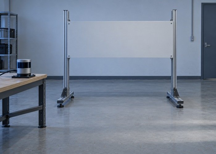
When Nav2 misses a tabletop edge or another overhanging obstacle that is visible in a 3D LiDAR cloud, check the transformed height of the returns against every vertical gate. Source height filtering, layer height limits, and voxel-grid coverage can each remove information before it reaches the two-dimensional costmap. Raising one maximum-height parameter does not necessarily widen the whole observation path.
Start from the robot’s physical collision envelope, including its payload and protruding equipment. Then use a stationary test with supported targets at known heights to compare raw points, transformed points, voxel occupancy, and the final costmap. A successful height-window test is integration evidence; it does not certify a robot for operation around people.
The 3D point-cloud navigation overview explains why returns above a planar scan matter. This guide addresses a narrower decision: which heights your configured Nav2 observation path retains, and how to verify that against the structure the robot can physically strike.
Define the collision envelope before choosing height bounds
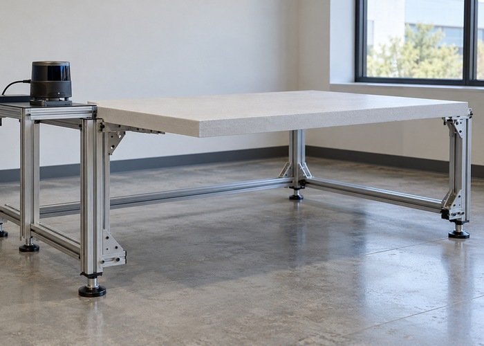
Measure the installed robot and its permitted payload configurations. Include the lowest relevant protrusion, the top of the load, brackets, and any structure outside the chassis outline. A target above the body can still be a collision hazard for a tall load. Conversely, geometry above the entire allowed envelope may not require the same treatment as a structure within it.
The Nav2 footprint guide describes planar footprint configuration. That footprint does not encode every vertical clearance relationship. Keep a separate height worksheet, and document how the chosen costmap representation conservatively covers the robot’s intended operating cases.
Do not use sensor mounting height as the upper obstacle limit. The scanner’s elevation and the object’s transformed elevation are different quantities. Relate the required observation region to actual route geometry using the doorway, elevator, and frame integration guide. Record which payload configuration each test represents.
Confirm the frame in which height is evaluated
A point’s raw z coordinate describes its height in the cloud’s frame. A tilted sensor can make an apparently low raw value correspond to a high point in the costmap frame. Inspect the mounting transform, axis convention, frame ID, and message stamp before assigning physical meaning to a height filter.
The Nav2 transformation guide establishes the frame relationships used by navigation. Confirm that transforms exist for the observation’s acquisition time. A correct transform at the current instant does not prove availability for a recorded or delayed message.
Place a rigid target at a measured height while the platform is immobilized. Compare its returns in the sensor frame and configured costmap frame. If the transformed height does not agree with the fixture geometry within your reference method’s tolerance, investigate the transform or measurement first. Changing height bounds to absorb a frame error creates an unexplained configuration.
Trace the source filter and the layer filter separately
The Jazzy observation-buffer implementation transforms the cloud to the configured global frame and retains points within the source height bounds. Thus, a point can be present in the published cloud but absent from the observation that the layer processes. Inspect the effective source namespace, not just a similarly named parameter elsewhere.
Next inspect the layer’s own maximum height and its marking configuration. The Jazzy voxel-layer implementation also checks point height and grid coordinates during marking. A source that accepts a point does not guarantee that the voxel layer will represent it.
| Boundary | Evidence | Question |
|---|---|---|
| Raw cloud | Target points and frame ID | Does the sensor observe the target at all? |
| Transformation | Points in the costmap frame | Does their height match the physical fixture? |
| Source height filter | Effective lower and upper bounds | Can the required returns enter the observation buffer? |
| Layer and voxel grid | Height limit, origin, resolution, and count | Can accepted returns be represented and marked? |
| Master costmap | Projected cell and contributing layers | Does the occupied region reach the map being inspected? |
Save this worksheet with the ROS distribution and Nav2 package revision. Parameters and implementation details are version-specific. Use the installed source and effective values when they differ from an example copied from a tutorial.
Calculate grid coverage and test its edges
The Jazzy voxel-layer documentation defines origin_z, z_resolution, and z_voxels, with a maximum of 16 vertical voxels. Treat voxel count as an implementation constraint rather than an unlimited height adjustment.
For an illustrative configuration, an origin of 0 metres, a vertical resolution of 0.1 metres, and 12 voxels describe a nominal span of 1.2 metres. This is a calculation example, not a recommended setting. Increasing a separate height limit above that span does not itself allocate additional vertical cells. Verify behavior near the grid boundaries rather than assuming an endpoint is included.
Changing resolution trades vertical detail against coverage for a fixed count. Record what distinction the application needs to preserve, then test it. Also review the column-marking threshold: a visible return can occupy a voxel without producing the costmap behavior you expected from the configured projection rule.
If a ground plane dominates the results, examine transformed ground height, lower bounds, and preprocessing. Avoid removing every low return merely to make the display look clean. Low obstacles can intersect the collision envelope too. The robot sensor-selection comparison helps frame the required geometry without prescribing a universal filter.
Use a low, middle, and high target matrix
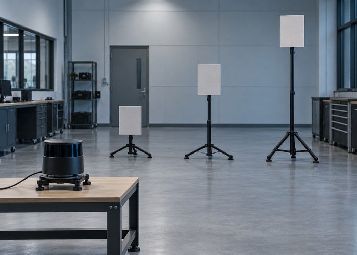
Keep the sensor and robot stationary. Use rigid, matte targets on stable supports at several measured heights, including locations near the intended bounds. Arrange the fixture so the sensor can observe the relevant surface rather than only the supporting legs. Record the distance, orientation, payload envelope, and expected map location for each case.
For each height, save the raw cloud, transformed target returns, voxel display when available, and final costmap. Begin with a simple unobstructed scene, then add the actual application’s materials and occlusions as separate conditions. A failure without raw target returns is a visibility problem to investigate before adjusting the costmap.
Run the matrix before and after one justified configuration change. Keep all other settings fixed and preserve unsuccessful runs. The pallet-handling test guide connects such observations to application acceptance criteria, which should be agreed before choosing a preferred result.
Separate height coverage from clearing and route qualification
Once the required targets are marked, remove them and inspect the clearing sequence separately. The Nav2 clearing diagnostic addresses retained occupancy after removal. Passing one test does not imply passing the other: an obstacle can be detected correctly and then remain stale.
Document whether your planar costmap conservatively blocks an overhang even where the bare chassis could pass underneath. If payload heights vary, define how configuration follows those states. Do not infer that a two-dimensional projection is a complete three-dimensional collision checker.
Keep the evidence package small enough to repeat: robot envelope, fixture dimensions, sensor transform, source and layer bounds, grid settings, package revisions, recordings, and observed pass or failure for every matrix row. Use that record when the mount, payload, driver, or navigation configuration changes.
Frequently asked questions
Why does RViz show an overhang that Nav2 misses?
The viewer may display the raw cloud while the costmap uses transformed, filtered observations. Trace the source and layer gates before concluding that the sensor failed.
Is increasing max_obstacle_height enough?
Only if that was the limiting gate. Source filtering, grid coverage, marking thresholds, or frame errors can still exclude the same target.
Should ground points always be discarded?
Choose filtering from the physical envelope and task. Check low hazards explicitly so a cleaner-looking cloud does not hide required geometry.
What should trigger another height-window test?
A changed sensor mount, payload envelope, driver preprocessing path, or costmap configuration. Repeat the same measured target matrix to make the comparison meaningful.