When two GMSL cameras appear to show the same picture, prove stream identity before replacing either camera. The duplicate can arise in the preview application, device selection, or the route through serializer, deserializer, CSI, and capture software. Two visible windows are not evidence of two independently routed sensors.
Give each camera a distinct stationary target, capture each physical link separately, and then repeat with both connected. Keep hardware identities, effective configuration, and output files together. The useful result is a reproducible map from a physical lens to an application stream, not a pair of attractive preview screenshots.
The Jetson BSP compatibility checklist covers whether the complete combination is supported. This guide starts after that baseline: the cameras can produce images, but the team needs to explain why the intended stream identities are lost.
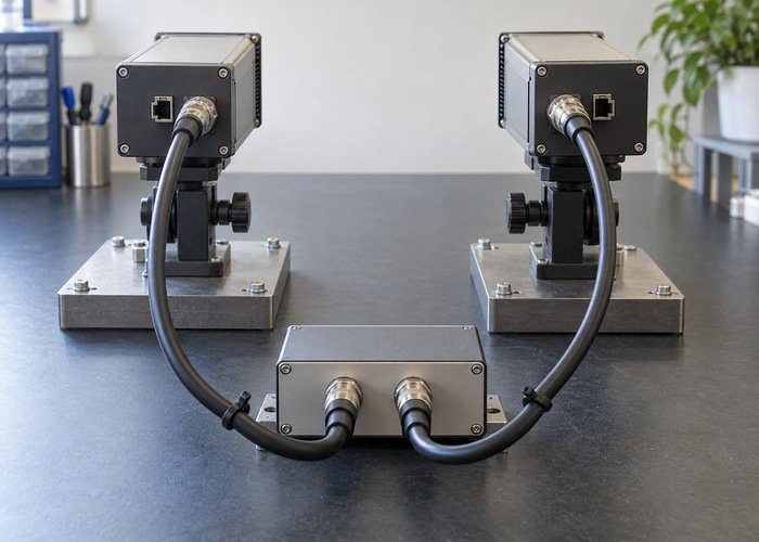
Distinguish identical scenes from duplicated streams
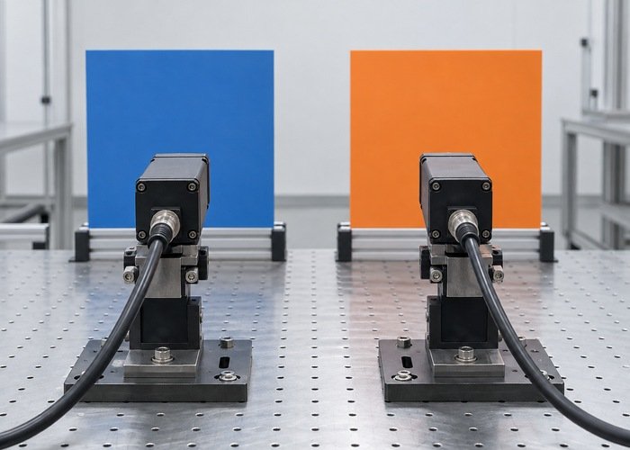
Place a blue matte target within one camera’s view and an orange target within the other’s. Separate the fields of view so each target’s presence is unambiguous. Use supported fixtures and follow the hardware connection procedure; power down before connection changes when required by the equipment.
Capture short files rather than relying only on live windows. Record the exact command, device or camera selector, output filename, and physical camera identity. If both files show one target, the fault is upstream of those files or in their selection. If the files differ but the windows match, investigate the display application first.
Check whether the application duplicates one input into two views, reuses a cached frame, or selects the same source twice. Save its effective arguments and configuration. Avoid changing device-tree values until the software selection has been established; otherwise a display mistake becomes mixed with a routing change.
Create a physical-to-logical route table
Record sensor and serializer identities, cable labels, deserializer input, output CSI port, virtual-channel assignment, receiver endpoint, capture node, and application selector. Add module, carrier, BSP, driver, and effective device-tree revisions. A route table should identify each boundary even where two streams share one physical output.
NVIDIA’s r36.4.4 GMSL reference guide distinguishes source and destination channel IDs and the matching receiver configuration. Use it as a versioned reference, not a universal register recipe for every SerDes combination.
| Boundary | Camera A | Camera B | Evidence |
|---|---|---|---|
| Physical sensor | Part and serial identity | Part and serial identity | Fixture and cable photographs |
| Deserializer input | Documented link label | Documented link label | Board documentation and effective link setup |
| CSI output | Output port and route | Output port and route | Carrier routing and driver configuration |
| Virtual channel | Source and destination IDs | Source and destination IDs | Effective configuration at both ends |
| Capture endpoint | Node or API identity | Node or API identity | Enumeration and topology snapshot |
| Application output | Selector and filename | Selector and filename | Distinct-target captured frames |
Keep unknown fields marked unknown. A camera label such as “front” does not establish a virtual-channel number, and a connector number does not automatically equal a video-node index. Compare the intended route with the effective route loaded by the running system.
The GMSL hardware shortlist should be accompanied by the exact sensor and interface documentation. Ask for the tested topology of that camera, serializer, deserializer, and board revision rather than borrowing another product’s mapping.
Identify capture endpoints without assuming their order
Inventory the nodes and their driver-reported identities. The Linux V4L2 interface documentation helps distinguish device interfaces; a pathname alone is not a physical-camera identity. Save enumeration after the relevant startup sequence and compare it with the route worksheet.
Where the platform exposes a media topology, retain it using the supported tooling for the installed package. The Media Controller API documentation describes connected media entities and links. Use that topology as evidence alongside captured images, not as a substitute for the distinct-target test.
For example, two application selectors may be aliases for one endpoint even though their display labels differ. Conversely, V4L2 nodes and an Argus application’s camera indices can represent different naming systems. Record each API’s selection method separately instead of equating their numbers by appearance.
Compare effective channel settings across the receiving path
For the installed driver, follow the sensor mode, SerDes route, CSI endpoint, and VI endpoint configuration. In the NVIDIA reference path, the corresponding virtual-channel settings must agree. Do not conclude that every camera in the system needs a globally unique ID: the receiver context and physical port sharing also matter.
The sensor-driver programming guide supplies version-specific mode and endpoint context. Compare the running device tree with the intended file. Editing an overlay that was never loaded does not test the routing hypothesis.
Check the deserializer’s exact operating mode and supported remapping behavior against its documentation. The GMSL2 manufacturer guide is a technical reference for link and aggregation concepts; device-specific constraints still belong to the actual parts used. Avoid undocumented register changes as a first diagnostic step.
Keep addressing and video routing separate in the worksheet. Successful control transactions to both sensors do not prove that their image streams reach distinct capture outputs. Likewise, a duplicated image does not by itself demonstrate a failed sensor or cable.
Run one-camera isolation, then paired validation
Start with only camera A enabled according to the supported procedure and capture its distinctive target. Record which endpoint produces it and whether other advertised endpoints remain active. Then repeat with only camera B. Preserve configuration and logs for both runs, including failed or unexpected outputs.
Next enable the supported pair without changing image modes or selectors. Verify that each captured output retains its physical target identity. Repeat the sequence after a normal restart so the result is not dependent on one accidental enumeration order. Document every reconnection or configuration change as a separate test.
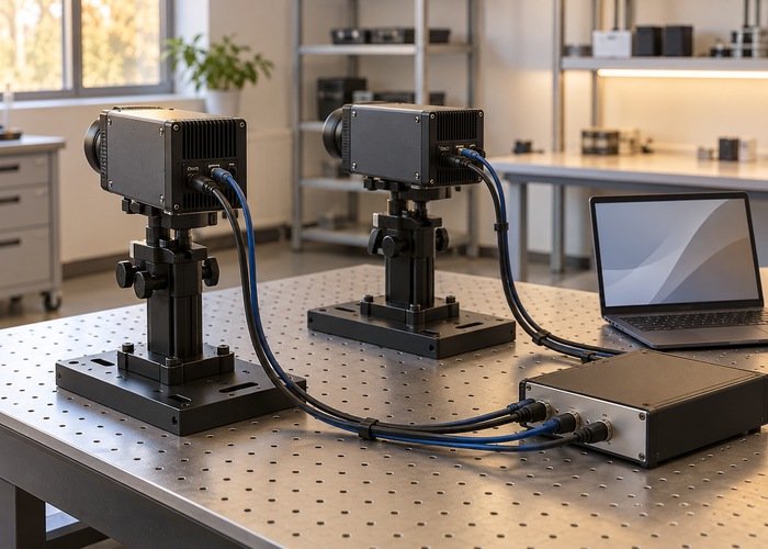
If mapping changes after a restart, compare endpoint enumeration and loaded configuration with the previous run before editing routing. Record whether the physical targets still follow the same outputs. A stable route table should describe both the successful steady state and the startup sequence that produces it.
Keep routing identity separate from synchronization
Different physical images prove stream separation, not synchronized acquisition. If the application needs fusion, establish timestamp semantics and triggering in a separate test. The sensor clock-check guide addresses that next boundary.
Likewise, a corrected stream mapping does not prove spatial alignment. Use the camera and LiDAR calibration workflow only after stream identity is stable. Calibration performed on mislabeled cameras can produce a consistent result assigned to the wrong physical lens.
For escalation, send the route table, part and software identities, effective configuration, media topology where available, exact capture commands, one-camera files, paired files, and the first boundary where identity changes. The carrier-board documentation should resolve physical routing questions for the proposed revision. Ask for a specific correction supported by that evidence.
Frequently asked questions
Do two video windows prove two cameras are active?
No. Verify distinct physical targets in separately identified captured outputs. The application can display one source twice.
Should I assign different channel IDs everywhere?
Match the supported routing plan and receiver context. Blind changes can break valid paths and hide the first error.
Is /dev/video0 permanently camera A?
Do not assume it. Retain enumeration, driver identity, topology, and a physical-target check for the startup sequence being tested.
Does fixing the duplicate stream prove synchronized capture?
No. Stream identity and acquisition synchronization need separate evidence, followed by calibration where the application requires it.