2D LiDAR + IMU + camera sensor fusion sounds like a software feature, but in an indoor robot it is really a discipline for keeping several imperfect measurements honest. A LiDAR scan can show walls and obstacles. An IMU can help with short-term rotation and motion changes. A camera can add visual context. None of them removes the need for good frames, timestamps, route tests, and clear behavior rules.
The quick answer is to start with a simple fusion goal. Do you need smoother odometry, better localization during turns, more stable navigation near glass, or richer obstacle understanding? A clear goal prevents the team from wiring every sensor into the system without knowing which problem each one solves.
Begin With The Route Problem
Indoor robots fail in recognizable places: shiny lobby floors, narrow hallways, elevator fronts, crowded cross paths, docking stations, and rooms with repeating walls. A robotics LiDAR project should identify those scenes before deciding how much fusion is needed. If the robot only needs planar obstacle awareness, LiDAR plus odometry may be enough. If it turns sharply, moves over uneven floors, or loses visual features, IMU and camera data may help.
The important question is not whether fusion sounds advanced. The question is what error you are trying to reduce. Wheel slip, yaw drift, missed low objects, visual ambiguity, and weak map alignment are different problems. Each needs a different test.

Give Each Sensor A Job
A 2D LiDAR sensor is usually strong at measuring distance in a plane. It helps with obstacle detection, mapping, and navigation around walls, carts, people, and furniture bases. An IMU measures acceleration and angular velocity, which can help smooth motion estimates when the robot turns or slips. A camera can help with visual features, signs, docking markers, object context, or depth if it is a depth camera.
The robot_localization documentation describes state estimation nodes for robots moving in 3D space. The Nav2 robot_localization guide explains using fused odometry from multiple inputs. That does not mean every sensor should be trusted equally. It means each measurement should be configured with the uncertainty and frame information it deserves.
| Sensor | Useful contribution | Common weak point |
|---|---|---|
| 2D LiDAR | Planar walls, obstacles, route geometry | Misses objects outside the scan plane |
| IMU | Short-term angular motion and acceleration | Drifts if used alone for position |
| Camera | Visual features, markers, object context | Sensitive to lighting, blur, and texture |
| Wheel odometry | Local movement estimate | Slips on smooth floors or loose surfaces |
| Fused odometry | Smoother local estimate | Only as good as timing and configuration |
Frames Are The First Fusion Test
Sensor fusion fails quickly when frames are vague. The LiDAR frame, camera frame, IMU frame, base_link, odom, and map frames need a coherent transform tree. The ROS 2 tf2 concept guide explains how transforms track coordinate frames over time, and REP 105 gives the mobile robot frame convention that keeps map, odom, and base_link understandable.
Measure the physical offsets rather than copying values from a sample file. If the camera is forward of the LiDAR, if the IMU is rotated inside the chassis, or if the sensor bracket is angled, the transform should reflect that. A few centimeters can matter near a dock, chair leg, or pallet corner.
Timestamp Problems Look Like Bad Sensors
A fusion pipeline can be mathematically sound and still fail if messages arrive with inconsistent timing. A scan from one moment, an IMU reading from another, and camera data delayed by processing can produce motion estimates that look jittery or late. Before changing hardware, check timestamps, computer load, driver settings, and network delays.
A practical test is to rotate the robot at a steady speed and watch whether LiDAR, IMU, and camera observations agree. If one stream lags behind the others, the robot may appear to slide or turn around the wrong point. That error becomes more visible in tight indoor routes.
Use LiDAR As The Grounded Route Sensor
For many indoor robots, LiDAR is the most grounded route sensor because it directly measures distance to surrounding geometry. The general LiDAR technology overview is useful for readers who want the basic sensing concept, but the project decision should come from the route. Can the scan see chair legs, bags, low boxes, door frames, and people at the height that matters?
If the answer is yes, LiDAR can anchor the navigation behavior. The IMU can help during quick turns or short odometry disturbances. The camera can add context where visual features are useful. If the scan plane misses the important objects, fusion will not magically recover what was never measured.
A Practical Indoor Pilot
Build a small route that includes a straight corridor, one tight turn, one docking surface, one side crossing, and one shiny or visually confusing area. Run the robot slowly first. Then run it at intended speed. Record scan stability, odometry smoothness, visual feature quality, and whether the robot behavior feels natural around people.
Use the LidarStar solutions page to frame the use case: service delivery, inspection, factory logistics, or autonomous movement in a public building. The route notes should use ordinary language. Write down where the robot hesitates, where localization drifts, and where it reacts too late or too often.
What To Fuse First
Start with wheel odometry and IMU if the robot already has decent wheel data but yaw is unstable. Add LiDAR-based localization or scan matching when the route has enough geometry and the robot needs map consistency. Add camera data when visual landmarks, docking targets, depth cues, or semantic context solve a specific problem.
Avoid a common mistake: adding a camera because it feels complete. If the lighting changes sharply, if the camera has motion blur, or if the route has repeated blank walls, camera data may not solve the first problem. A clean LiDAR and IMU setup can be a better first milestone.
How To Review Fusion Quality
Fusion quality should be reviewed with field symptoms. Does the robot turn around its actual center? Does the map stay aligned after a loop? Does the robot remain calm near people? Does it dock repeatably? Does the estimate become worse when one sensor is blocked or delayed? Those questions are easier to act on than a vague statement that localization is noisy.
The Nav2 navigation concepts documentation explains that costmap layers can use information from LiDAR, radar, sonar, depth images, and other inputs. That is a useful reminder: fusion is part of the whole navigation behavior, not a separate trophy feature.

Selection Notes For Hardware Buyers
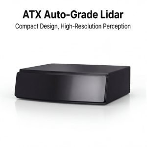
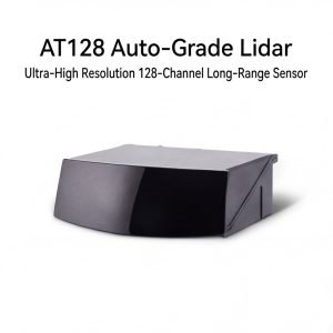
When reviewing the LidarStar product catalog, describe the route before asking for a sensor recommendation. Include robot speed, mounting height, smallest obstacle, expected indoor lighting, floor material, computer platform, and whether the project needs mapping, obstacle detection, docking, or all three.
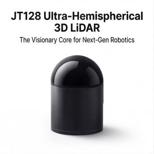
For projects that may need richer depth data, compare the route against 3D LiDAR sensor options. If the problem is mostly planar navigation, a well-mounted 2D sensor with good timing and a clear fusion plan may be the more practical starting point.
Field Notes To Capture During The Pilot
A useful pilot log is short, factual, and tied to the route. For 2D LiDAR + IMU + camera sensor fusion, record the mounting position, object used in the test, robot speed, lighting or floor condition, software version, and the result you observed. Avoid vague notes such as “worked” or “failed.” Write what happened: the robot saw the low carton at the first mark, the scan jumped near the glossy threshold, the estimate drifted after the second turn, or the cloud kept rack legs but removed isolated dust points.
Photos matter because they keep the team honest. Take a front view, side view, sensor close-up, route view, and problem-object view. If the test includes a dock, rack, elevator, doorway, or outdoor transition, photograph that scene from the robot’s height as well as from a standing human view. The robot does not experience the world from eye level, and many early mistakes come from reviewing a route from the wrong height.
A short phone video is often more useful than a long written report. Walk behind the robot during one clean run and one difficult run. Keep the target object in view. When the robot hesitates, stops, or recovers, say the scene out loud. Those details help engineering, operations, and purchasing discuss the same evidence instead of debating memory from a demonstration.
A Simple Acceptance Checklist
Before calling the pilot ready, run the same route at least three times without changing the setup. The robot should behave consistently in clean conditions, then continue to behave reasonably when a realistic object is added. If the result changes every run, do not tune around the problem yet. First find whether the variation comes from mounting, timing, calibration, floor condition, object placement, or software state.
The checklist should include detection, stability, response, recovery, and maintenance. Detection asks whether the system sees the target object. Stability asks whether the measurement stays believable while the robot moves. Response asks whether the robot slows, stops, maps, or classifies in a useful way. Recovery asks whether the robot returns to normal behavior after the event. Maintenance asks whether the setup can be inspected and cleaned without special effort.
| Acceptance area | Question to answer | Good evidence |
|---|---|---|
| Detection | Does the system see the object that matters? | Repeated observations at known positions |
| Stability | Does the data stay calm during motion? | No unexplained jumps during turns or vibration |
| Response | Does the robot behave naturally? | Smooth slowdown, clean map update, or correct classification |
| Recovery | Does the robot continue after the event? | Normal route behavior resumes without manual reset |
| Maintenance | Can the setup be kept clean and aligned? | Clear access to window, bracket, cable, and fasteners |
Mistakes That Create False Confidence
The easiest mistake is testing only the cleanest version of the route. A clear hallway, empty aisle, or perfect lab floor can hide the exact problem that will appear during daily use. Add ordinary clutter early: a bag near the path, a carton half inside the lane, a chair leg, a dark object, a shiny edge, or a person crossing from the side. The test should look like normal work, not a showroom.
Another mistake is separating sensor review from robot behavior. A signal can look good in visualization while the robot still moves poorly. A robot can also move acceptably in one narrow case while the data contains errors that will fail later. Review both layers together. Ask what the sensor measured, how the software interpreted it, what behavior followed, and whether that behavior fits the site.
Teams also create false confidence by changing too many things between runs. If mounting height, route speed, filter setting, and object position all change at once, nobody knows what caused the improvement. Change one variable, write it down, and repeat the same scene. Slow testing is often faster than a week of confused tuning.
How Operations And Engineering Should Review The Same Test
Engineering usually looks at frames, timestamps, noise, calibration, filtering, and compute load. Operations usually looks at whether the robot interrupts people, blocks a lane, hesitates in a bad place, or requires extra attention. Both views are necessary. A technically clean setup that annoys operators will not scale. A route that feels smooth but depends on fragile data will not survive a larger rollout.
During review, ask each group to name one pass condition and one concern. Engineering might require stable data at the intended speed. Operations might require the robot to wait before an elevator without blocking the main path. Maintenance might require access to clean the sensor window. Purchasing might require the setup to repeat across future robot builds. The final decision should include all four perspectives.
If the teams disagree, return to the route evidence. Replay the video, check the log, inspect the saved data, and retest the disputed scene. The goal is not to win an argument. The goal is to make the sensor decision visible enough that the next action is obvious.
What To Improve Before Scaling
Scaling should wait until the team can explain both strengths and limits. It is acceptable to know that the setup works best on one route type and needs more testing elsewhere. It is risky to scale when the team cannot explain why a false stop happened, why a map shifted, why a filter removed an object, or why the robot behaved differently on the second shift.
Before scaling, document the mounting drawing, cable route, software version, frame names, filter settings, test objects, route photos, and known limits. Store the daily inspection steps in plain language. A future technician should know what a clean sensor window looks like, what cable strain to avoid, and what route symptom suggests alignment has changed.
The strongest projects do not depend on one person remembering the setup. They leave a trail that another engineer can repeat. That trail is what turns a promising pilot into an operational system.
Handoff Package For The Next Engineer
A good handoff package for 2D LiDAR + IMU + camera sensor fusion should include the final article-like summary of the route, but it also needs engineering facts. Save the sensor model, wiring notes, host computer details, interface settings, mounting measurements, coordinate frames, selected parameters, and the reason each important setting was chosen. If the project later has a fault, these notes shorten troubleshooting dramatically.
Also include the negative results. If one mounting height missed low objects, write that down. If one filter setting removed useful edges, keep the example. If one route section caused repeated hesitation, save the video. Negative tests prevent future teammates from repeating work that already taught the project something important.
Finally, mark what still needs a longer trial. Short pilots are useful for setup decisions, but they cannot reveal every shift change, cleaning routine, lighting change, surface condition, or maintenance habit. A clear handoff separates what is proven from what still deserves monitoring.
That distinction helps the next review stay practical. It also keeps the team from treating a promising first route as proof for every future environment.
Conclusion
2D LiDAR + IMU + camera sensor fusion works best when every sensor has a job, every frame is measured, every timestamp is checked, and every route test has a reason. The result is not a stack that looks complicated. The result is an indoor robot that moves in a way people can understand and operators can maintain.
FAQ
Can an IMU replace wheel odometry for indoor robot localization?
Usually no. An IMU is valuable for short-term motion, but position estimates drift quickly without other measurements.
Should every indoor robot use a camera with LiDAR?
No. Use a camera when visual context, markers, depth, or object recognition solves a defined route problem.
What is the first sign of a frame problem?
Objects appear shifted, mirrored, or delayed in visualization, especially when the robot turns near known objects.
How do I test whether fusion helped?
Repeat the same route before and after the change, then compare alignment, docking, smoothness, false stops, and recovery after turns.
What should I send for a fusion recommendation?
Send route video, sensor positions, robot dimensions, current frame tree, topics, computer platform, and the exact failure you want to reduce.