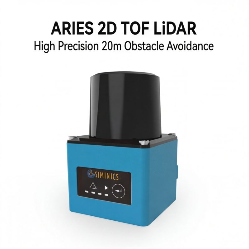
Most autonomous robots are built to see far — but the collisions happen close. That fundamental mismatch defines one of the most underappreciated risks in modern robotics, and it’s why 3D blind spot compensation LiDAR is rapidly shifting from optional upgrade to core safety requirement.

Long-range LiDAR systems are architecturally optimized for the horizon, not the floor. A typical 3D LiDAR unit — even a high-channel, 360° rotating sensor — is mounted at vehicle height and oriented to cover threats at distance. Its vertical field of view (FoV), commonly between 25° and 40°, is centered on the midplane of travel. The geometry works brilliantly at 10, 20, or 50 meters. It fails quietly at 0.5.
The perceptual vacuum is the term for what happens in that dead zone: the volume of space directly surrounding a moving robot where sensor coverage thins out or disappears entirely. Traditional sensor suites commonly leave gaps within 0.5 to 2 meters of the vehicle — exactly the range where low-profile obstacles, pedestrian feet, and rogue pallets live.
Why does this gap exist? A few compounding factors:
- Angular resolution loss — at close range, even a dense point cloud spreads its beams too wide to resolve small objects near ground level
- Mounting geometry — sensors aimed at the midfield create downward occlusion cones directly beneath and beside the chassis
- Scan pattern bias — most LiDAR configurations dedicate their densest vertical layers to elevated, distant targets rather than ground-adjacent space
- Near-field return noise — some units apply minimum-range filtering that discards returns closer than 0.5–1 meter entirely
The result is a robot that confidently maps the room but can’t reliably detect what’s at its own wheels. Solutions like single-plane scanning address parts of this challenge but cannot reconstruct the full three-dimensional picture close-range environments demand.
The consequences of this perceptual vacuum aren’t theoretical — they’re playing out daily on warehouse floors, and the costs are steeper than most operations realize.
The High Cost of Near-Field Invisibility in Industrial Environments
Blind spots in autonomous systems aren’t just a sensor engineering problem — they’re a direct liability that hits safety records, operational budgets, and regulatory standing simultaneously.
Blind spots in heavy machinery and commercial vehicles contribute to over 30% of side-collision accidents in industrial environments. That number becomes even more alarming when applied to fast-moving warehouse floors where AGVs, forklifts, and human workers share the same lanes with minimal margin for error.
Near-field LiDAR for autonomous robots addresses exactly this gap — but only when it’s designed to cover the zones that long-range sensors structurally ignore.
The downstream cost of those collisions compounds quickly. What begins as a single impact event typically triggers a cascade of operational disruptions:
- Unplanned downtime that can idle an entire warehouse zone while incident reports are filed and equipment is inspected
- Inventory damage from tipped pallets, crushed goods, or derailed conveyor systems
- Worker injury claims that escalate insurance premiums and invite regulatory audits
- OSHA compliance exposure, since failure to maintain adequate machine safeguarding directly violates General Industry Standard 1910.212
“Employers must ensure that machines are adequately guarded to protect workers from hazards such as those created by point of operation, ingoing nip points, rotating parts, and flying chips and sparks.” — OSHA Machine Guarding Standard 1910.212
Low-profile obstacles are the primary victims of near-field blind zones. Ground-level pallets, small AMRs, floor-mounted fixtures, and cable trays routinely fall below the detection cone of sensors optimized for mid-to-long-range scanning. Understanding how 2D and 3D sensor architectures differ in this respect is essential — because a sensor that maps a clear corridor at 30 meters may be entirely blind to a pallet sitting 1.5 meters from its own chassis.
Solving this requires rethinking the sensor itself — its geometry, its coverage angles, and how it processes near-field spatial data.
Anatomy of a 3D Blind Spot Compensation Sensor
Blind-spot compensation sensors are purpose-built around a core engineering principle: see what’s close, see what’s below, and see it completely. This is precisely where LiDAR blind zone reduction technology diverges sharply from standard long-range sensing.
Vertical FoV is the defining specification. Standard long-range LiDAR systems typically operate with a vertical field of view between 20 and 40 degrees — enough to map distant obstacles at road level, but inadequate for the steep downward angles required near a robot’s chassis. According to research published by IEEE, blind-spot compensation sensors are specifically engineered with vertical FoVs often exceeding 70 to 90 degrees. That range is not incidental — it’s the minimum geometry needed to eliminate the chassis gap that previous sections identified as the source of high-consequence near-field collisions.
| Specification | Standard Long-Range LiDAR | Blind-Spot Compensation Sensor |
|---|---|---|
| Vertical FoV | 20°–40° | 70°–90°+ |
| Optimal detection range | 30–200m | 0.1–15m |
| Point cloud density (near-field) | Low | High |
| Scanning method | Mechanical rotation | Hemispherical / solid-state |
| Primary use case | Path planning | Proximity safety |
Point cloud density matters as much as angular coverage. In the near field — within 1 to 5 meters of the robot body — a sparse point cloud leaves dangerous spatial gaps between returns. High-density near-field sensing fills that volume with enough data points to resolve low-profile objects: a fallen tool, a crouching technician, a pallet corner protruding into the travel lane.
Hemispherical scanning replaces the limitations of mechanical rotation by covering a continuous downward arc rather than a fixed horizontal plane swept in a circle. Mechanical systems spin fast but scan thin; hemispherical designs sweep volume. For engineers building safety-certified autonomous systems, that volumetric awareness is non-negotiable.
The mechanical components behind traditional rotation, however, raise a separate reliability concern — one that becomes critical in 24/7 industrial environments.
The Shift to Solid-State: Reliability in High-Vibration Settings
Solid-state LiDAR isn’t just a hardware upgrade — it’s the foundational reliability shift that makes knowing how to eliminate LiDAR blind spots in AGVs a solvable engineering problem rather than an ongoing operational risk.
Mechanical spinning sensors were never designed for factory floors. Traditional rotating LiDAR units rely on precision bearings, motor assemblies, and exposed optical elements that cycle thousands of revolutions per hour. In a controlled lab, that’s manageable. In a 24/7 manufacturing environment — where AGVs traverse uneven surfaces, dock repeatedly against loading bays, and absorb constant vibration from nearby machinery — those moving parts become a failure point. Bearing wear accelerates. Alignment drifts. Detection consistency degrades before any fault flag appears in diagnostics.
MTBF gap: This is where solid-state architecture makes a quantifiable difference. Without rotating components, solid-state sensors eliminate the primary mechanical wear vectors entirely. As noted by the Sensors Journal (MDPI) confirms, solid-state and wide-angle 3D LiDARs deliver superior reliability in high-vibration industrial settings compared to traditional mechanical spinning sensors — a gap that translates directly into longer maintenance intervals and fewer unplanned downtime events. In continuous-operation environments, that MTBF advantage compounds quickly across a fleet.
Vibration resistance is equally critical. Industrial floors carry vibration signatures from conveyor systems, press machinery, and heavy forklifts operating in parallel. Solid-state sensors, built on photonic integrated circuits or MEMS-based architectures, are inherently immune to the resonance frequencies that degrade mechanical sensor calibration over time. The result is stable, repeatable near-field point-cloud data — even in the harshest operational conditions.
For L4 autonomy specifically, this reliability profile isn’t a nice-to-have. It’s a prerequisite. A solid-state sensor designed for autonomous systems must perform identically on day one and day three hundred. Any degradation in near-field coverage creates the same perceptual gaps discussed earlier — only now they appear silently, without warning.
Solid-state hardware is the only credible foundation for blind-spot compensation at industrial scale. Understanding that foundation, however, is only half the equation — the other half is how near-field sensor data actually gets woven into the broader autonomy stack.
Integrating Near-Field Sensors into the L4 Autonomy Stack
Integrating near-field sensors into a Level 4 autonomy stack isn’t a plug-and-play exercise — it demands deliberate architectural planning across both hardware and software layers.
Sensor fusion is the starting point. Long-range LiDAR handles highway-speed obstacle detection and path planning, but it leaves a critical gap beneath two meters and within a few feet of the platform’s body. Short-range wide-angle LiDAR sensors fill that gap by feeding dense, low-latency point clouds into the same perception pipeline. The fusion layer must reconcile these two data streams — different update rates, different field geometries — into a single coherent occupancy map without introducing latency spikes that downstream planners can’t tolerate.
That coherent map becomes especially important during complex, high-stakes maneuvers. Docking sequences, tight lane changes, and reverse approaches all share one dangerous characteristic: the robot’s own chassis geometry creates a perceptual vacuum directly around its base and corners. Long-range sensors are simply pointed the wrong direction. As Autonomous Vehicle International notes:
“The integration of dedicated near-field sensors is no longer optional for Level 4 autonomy; it is the primary safeguard for complex maneuvers like lane changes and docking.”
Closing that perceptual vacuum requires a three-step integration approach:
- Hardware placement audit — Map every blind zone around the platform at operating height and confirm short-range sensor mounting angles cover those zones with sufficient overlap.
- Data pipeline alignment — Synchronize near-field point clouds with the main perception stack using timestamped fusion, ensuring no frame mismatch between sensor modalities.
- Behavior tree updates — Revise the motion planner’s low-speed logic so it queries near-field occupancy data exclusively during docking, reversing, and lane-change triggers, reducing reliance on extrapolated long-range data.
Hardware/software synergy isn’t optional — it’s the mechanism that turns raw sensor data into actionable safety decisions. You can browse current LiDAR sensor portfolios to evaluate which near-field units align with your stack’s integration requirements.
The real-world payoff of this architecture becomes clearest when you examine specific deployments — and few platforms stress-test near-field integration harder than automated guided vehicles operating on live factory floors.
Case Study: Eliminating Blind Spots in Automated Guided Vehicles (AGVs)
Blind-spot compensation isn’t a theoretical advantage — in AGV deployments, it’s the difference between continuous uptime and costly, liability-heavy collisions.
Before compensation sensors: A typical AGV relies on a single forward-facing LiDAR unit mounted at chest height. The sensor sweeps a clean horizontal plane ahead of the vehicle, but the geometry creates critical vulnerabilities. Low-profile obstacles — pallets flush to the floor, steel corner guards, crouched maintenance workers — fall entirely outside the detection cone. The result is a predictable pattern: the robot moves confidently into hazards it literally cannot see.
After 3D blind-spot compensation: Wide-angle supplementary sensors mounted near the vehicle’s base extend the perceptual field downward and laterally. In practice, this means a sensor angled at roughly 20–30 degrees below horizontal can resolve objects as flat as 10 cm off the ground surface. The AGV’s perception stack receives a fused point cloud that wraps around the chassis — no geometric shadow, no unchecked corridor.
The safety impact compounds quickly. According to the Robotics and Automation Society, implementing 3D blind-spot compensation reduces “no-go” zones to near zero, directly lowering the frequency of pedestrian collisions in mixed-use environments. Eliminating no-go zones means the fleet operates on its planned route, not a rerouted workaround path that bleeds time and throughput.
ROI here is concrete. A single industrial forklift or AGV collision carries an average total cost — downtime, equipment repair, regulatory review, and potential workers’ compensation — that easily exceeds $50,000 per incident. For a warehouse running 20 AGVs on overlapping shifts, preventing even two incidents annually more than covers a full sensor upgrade cycle.
As LiDAR hardware has transitioned from R&D prototypes to production-grade components, the cost barrier for this kind of multi-sensor redundancy has dropped substantially — making full-perimeter coverage increasingly standard rather than exceptional.
Selecting the right hardware for that coverage, however, raises a procurement question that engineering teams can’t afford to treat as an afterthought.
Procurement Strategy: Direct-to-Factory vs. Intermediaries
Choosing where to source near-field LiDAR hardware is as strategically important as choosing which sensor to deploy — the wrong procurement path inflates costs and delays timelines.
Eliminating intermediaries from the supply chain can reduce per-unit sensor costs by 15–30%, a margin that compounds significantly across fleet-scale deployments. Traditional distribution channels add markup at every handoff — regional distributors, value-added resellers, and import brokers all extract margin before hardware reaches an engineering team. For R&D programs operating on fixed budgets, that overhead often means fewer prototype iterations or compromised sensor specifications.
Certification rigor is non-negotiable when sourcing hardware for autonomous platforms. Triple-certified sensors — validated against automotive-grade standards for vibration tolerance, temperature range, and electromagnetic compatibility — aren’t a premium feature. They’re a baseline requirement for any deployment that must demonstrate functional safety compliance. Procuring directly from manufacturers or factory-authorized partners ensures certification documentation is traceable, unmodified, and audit-ready. Intermediaries occasionally repackage or rebundle hardware in ways that complicate provenance verification, creating liability exposure during safety audits.
Technical support latency is another underestimated procurement risk. Global R&D projects frequently span multiple time zones, and sensor integration challenges don’t respect business hours. A 48-hour support response from a regional distributor can stall an entire sprint cycle. Sourcing through partners that offer 24-hour direct technical access — staffed by engineers familiar with the hardware’s firmware and integration interfaces — keeps development velocity high.
This is where factory-direct sensor distributors create measurable value. LidarStar partners directly with manufacturers like RoboSense and Hesai to offer automotive-grade 3D sensing solutions at factory-direct prices — removing intermediary markup while maintaining full certification traceability and round-the-clock engineering support.
A streamlined procurement checklist for near-field LiDAR:
- Verify certification lineage — confirm ISO and automotive-grade documentation is manufacturer-issued
- Confirm factory-direct pricing — request a quote directly against manufacturer MSRP
- Evaluate support SLAs — prioritize 24-hour technical response guarantees
- Assess integration resources — SDK availability, ROS compatibility, and application engineering support
These procurement decisions ultimately shape how quickly sensor data translates into a reliable, validated autonomy stack — the bottom line every robotics engineer needs to keep in focus.
The Bottom Line: Key Takeaways for Robotics Engineers
3D blind-spot compensation has moved from competitive differentiator to non-negotiable safety baseline — and engineers who treat it as optional are designing for failure.
The evidence across sensor physics, AGV deployments, and procurement strategy converges on a consistent set of principles. Here’s what every robotics engineer should carry forward:
- Near-field zones are the leading collision risk. Blind zones in the 0.5m–2m range account for roughly 30% of industrial collisions — a number too significant to address with software workarounds alone. Hardware-level coverage is the only reliable fix.
- Vertical FoV is the defining spec. As IEEE Xplore research confirms, 3D blind-spot LiDARs rely on ultra-wide vertical fields of view — exceeding 70 degrees — to eliminate near-field detection gaps. A sensor with impressive horizontal range but narrow vertical FoV will still leave dangerous dead zones around a robot’s chassis.
- Solid-state sensors win in harsh conditions. In high-vibration environments — conveyor lines, loading docks, outdoor AGV yards — solid-state units deliver meaningfully higher MTBF than mechanical alternatives. For engineers comparing sensing architectures, the tradeoffs between rotating and solid-state designs deserve careful attention before spec-locking a platform.
- L4 autonomy demands dedicated near-field sensing. Relying on a primary long-range LiDAR to double as a proximity sensor is a design compromise, not a solution. L4 autonomous maneuvers — reversing, rotating, narrow-aisle navigation — require purpose-built near-field safeguards as a mandatory system layer, not an afterthought.
- Direct-to-factory procurement protects R&D budgets. As covered in the previous section, sourcing sensors directly from manufacturers reduces per-unit costs and accelerates iteration cycles without any sacrifice in sensor quality or certification integrity.
In practice, these five principles form a decision framework that applies whether you’re speccing a new AMR platform or hardening an existing fleet. The questions that remain — which sensor geometries work best, how environmental factors affect performance, and what makes vertical FoV uniquely critical — are exactly where the FAQ section ahead picks up.
Frequently Asked Questions About Blind Spot LiDAR
The right sensor answers depend on your geometry, environment, and motion profile — not just spec-sheet comparisons.
Q: What is the difference between 2D and 3D blind spot sensors?
2D sensors scan a single horizontal plane, detecting obstacles only at one fixed height. If a hazard sits above or below that plane — a low pallet, a child crouching, or an elevated obstacle — the sensor misses it entirely. 3D sensors capture a volumetric point cloud across multiple vertical layers, eliminating the elevation blind spots that flat-plane scanning cannot address.
Q: Can one sensor cover the entire perimeter of an AGV?
Not reliably. A single sensor’s horizontal FoV rarely exceeds 360°, and mounting obstructions create shadow zones regardless. In practice, most AGV safety architectures combine two to four sensors, positioned at corners or staggered elevations, to achieve full perimeter coverage without dead zones.
Q: How does weather affect near-field LiDAR performance?
Rain, fog, and dust scatter laser pulses, generating false returns or degrading range accuracy. Near-field sensors are somewhat more resilient because shorter return times reduce accumulated scatter error. However, IP67-rated enclosures and adaptive filtering algorithms remain essential for reliable outdoor or dusty warehouse operation.
Q: Why is vertical FoV more important than horizontal FoV for blind spots?
Horizontal coverage is easily supplemented by adding sensors. Vertical FoV, however, determines whether the sensor detects floor-level hazards, low-clearance obstacles, or objects partially occluded beneath the robot’s chassis — gaps that occlusion research confirms are the most dangerous in dynamic environments. A narrow vertical FoV is the single biggest source of undetected near-field collisions.
Q: Where can I watch a visual explanation of how this works?
The following video explains the core mechanics of 3D LiDAR blind spot compensation:
[YouTube Embed: "How 3D LiDAR Blind Spot Compensation Works" — https://www.youtube.com/watch?v=q9PYHTz7uCg]
For engineers sourcing certified hardware across global deployments, LidarStar provides triple-certified sensors and expert technical consulting across 26+ countries — facilitating faster compliance and integration.