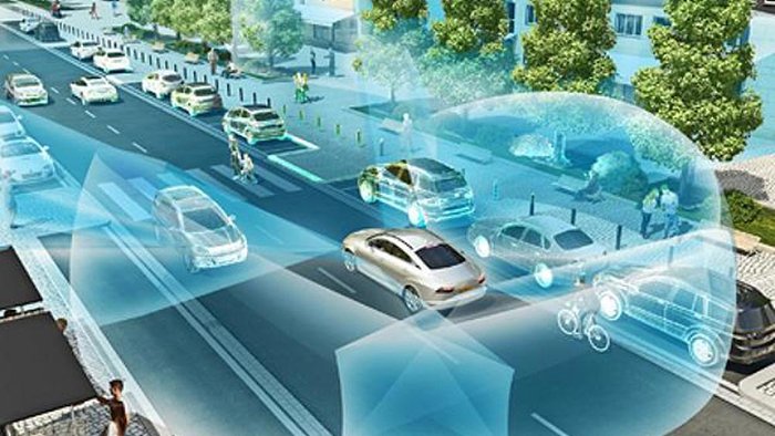
Mechanical LiDAR’s spinning mirrors and rotating assemblies were always a compromise — a workaround that the industry treated as permanent until something fundamentally better arrived.
Flash LiDAR is that something better. Rather than sweeping a laser beam point-by-point across a scene — a process that introduces latency, mechanical wear, and vulnerability to vibration — flash LiDAR fires a single diffused pulse that illuminates the entire field of view simultaneously. The result is an instantaneous 3D frame captured in nanoseconds, not milliseconds. As documented, this non-scanning architecture eliminates motion blur entirely, a critical advantage when the sensor is mounted on a vehicle traveling at highway speed or a drone navigating a dynamic environment.
The contrast with legacy mechanical scanning is stark:
- Mechanical scanning builds a scene sequentially, pixel by pixel, creating a window where fast-moving objects shift position mid-capture
- Flash capture records every point in the field of view at the same instant, producing coherent, time-consistent depth maps
- Solid-state construction removes rotating parts altogether, cutting failure modes and enabling form factors that fit inside a vehicle’s body panels
This architectural leap matters most when the systems consuming sensor data grow more sophisticated. AI-driven frameworks — the class of machine-learning pipelines now driving autonomous vehicles, surgical robots, and warehouse automation — depend on high-fidelity, real-time perception data to make safe decisions. A point cloud with temporal inconsistencies or mechanical-failure risk is a liability these systems cannot absorb. You can see how 3D depth sensing shapes safety-critical decisions at the Level 3 autonomy threshold, where human fallback shrinks and sensor reliability must expand to compensate.
The thesis of this article is direct: reliability and speed are the new benchmarks for autonomous sensing hardware, and solid-state flash LiDAR is the only architecture engineered from the ground up to meet both. Understanding why starts with exactly how this technology captures a scene — which is where the next section begins.
How Flash LiDAR Works: The 3D Camera Analogy
Flash LiDAR transforms an entire scene into depth data in a single burst of light — no scanning, no sweeping, no mechanical compromise.
The core insight: Flash LiDAR is essentially a 3D camera where each pixel provides both intensity and distance information, as Laser Focus World describes. That analogy isn’t just illustrative — it’s technically precise, and it explains why the architecture is so fundamentally different from mechanical alternatives.
The Mechanism of Diffused Light
Rather than concentrating laser energy into a single rotating beam, Flash LiDAR fires a broad, diffused pulse that illuminates the entire field of view simultaneously. A detector array — essentially a grid of photodetector pixels — then receives the returning photons from every point in that scene at once. Each pixel independently records two values: return signal intensity and time-of-flight distance.
The capture sequence works like this:
- Pulse emission: A nanosecond-scale laser burst floods the full FOV with diffused infrared light
- Simultaneous return: Reflected photons hit the detector array across all pixels at the same instant
- Per-pixel time-of-flight measurement: Onboard circuitry calculates distance for every pixel based on return delay
- Frame assembly: Intensity and depth values combine into a complete 3D point cloud — in a single exposure
Nanosecond-scale capture is what prevents the rolling shutter distortions that plague mechanical systems. Because every pixel fires and receives simultaneously, there’s no temporal offset between data points — the entire frame represents the same moment in time.
This architecture also enables meaningful miniaturization. Without spinning mirrors or rotating assemblies, optical components can be integrated into compact, ruggedized housings. When comparing flash lidar vs scanning lidar on physical footprint alone, solid-state designs offer dramatically smaller form factors — a practical advantage explored across solid-state LiDAR applications in aerial and ground-based robotics alike.
That simultaneity advantage, however, becomes even more critical when systems are moving at speed — which is exactly where mechanical scanning reveals its deepest flaw.
Flash vs. Scanning LiDAR: Solving the Motion Distortion Crisis
Scanning LiDAR’s fundamental flaw isn’t resolution or range — it’s time: the sensor can’t capture all points simultaneously, and that gap is where autonomous systems fail.
Point cloud warping is the direct consequence of mechanical rotation at speed. As a spinning LiDAR completes its sweep, a vehicle traveling at highway velocity moves several centimeters between the first and last point captured. The resulting point cloud is geometrically “smeared” — objects appear stretched, tilted, or displaced from their actual positions. At 70 mph, this distortion isn’t a minor calibration issue; it’s a safety-critical misrepresentation of the environment.
Understanding how flash LiDAR works makes the solution obvious. Because the sensor illuminates the entire scene in a single burst and captures every pixel at the exact same nanosecond, there is no inter-frame movement to distort. Experts note that Flash LiDAR sensors are entirely immune to motion distortion — the rolling-shutter effect that plagues mechanical systems simply has no mechanism to occur.
| Attribute | Scanning LiDAR | Flash LiDAR |
|---|---|---|
| Capture method | Sequential point-by-point | Simultaneous full-frame |
| Motion distortion | High at speed | None |
| Moving object accuracy | Degraded | Preserved |
| MTBF | ~1,000–3,000 hrs (mechanical) | 100,000+ hrs (solid-state) |
| Dangerous blind spots | Yes — during rotation gap | Minimal |
Reliability follows the same logic. Mechanical spinning assemblies introduce bearings, motors, and rotating contacts — each a failure vector. Solid-state LiDAR architectures achieve mean time between failures exceeding 100,000 hours, a figure mechanical systems can’t approach. In automotive-grade deployments, that difference determines whether a sensor survives a vehicle’s service life.
Dangerous blind spots emerge in scanning systems during the rotation gap — the moment between sweeps when new obstacles can enter a scene undetected. For a pedestrian stepping off a curb or a vehicle merging aggressively, that gap can be decisive.
Of course, Flash LiDAR’s simultaneous illumination model introduces its own engineering challenge worth examining closely: managing power density across a wide field of view.
The Range Reality: Managing the Flash LiDAR Trade-off
Flash LiDAR range has one genuine engineering constraint: flooding a wide field of view with light simultaneously demands far more photon energy than a focused scanning beam requires.
The physics are straightforward. When a scanning system concentrates its laser pulse on a narrow point, it achieves high power density almost by default. Flash LiDAR must spread that same energy across the entire scene at once, diluting intensity per unit area and reducing how far usable returns travel. In early implementations, this capped effective range at roughly 50–100 meters — workable for close-quarters robotics, limiting for highway-speed autonomy.
Modern component advances are steadily pushing that ceiling upward. Two technologies are doing the heaviest lifting:
- VCSEL arrays (Vertical-Cavity Surface-Emitting Lasers) now deliver tightly controlled, high-power pulses across large apertures with dramatically improved efficiency, enabling stronger illumination without proportional heat penalties.
- SPAD detectors (Single-Photon Avalanche Diodes) operate at single-photon sensitivity, extracting usable depth signals from return levels that would have registered as noise in earlier detector designs.
Together, these advances — well documented in ongoing coverage of solid-state sensor progress — are extending Flash LiDAR’s effective range into the 150–200 meter band for automotive-grade hardware.
Near-field performance remains Flash LiDAR’s uncontested strength. As Laser Focus World notes, Flash LiDAR is the most robust solution for near-field blind spot detection precisely because its solid-state architecture eliminates moving parts — delivering instant, complete spatial awareness in the critical zero-to-30-meter zone where pedestrians, cyclists, and merging vehicles appear with little warning.
In practice, the most capable autonomous sensor suites treat this not as a limitation but as a design principle. A hybrid architecture pairs Flash LiDAR’s dense, distortion-free near-field coverage with a long-range scanning system handling the horizon. Each technology does what it does best. As you’ll see, this clean division of labor becomes especially important when AI models enter the picture — because the quality of near-field data has consequences that ripple far beyond the sensor itself.
AI-driven and the 2025 Hardware Mandate
In 2025, the convergence of AI and physical-world sensing is creating a new hardware standard — and flash lidar technology sits at its center.
Data fidelity is no longer optional for AI systems; it’s the baseline requirement. The AI for Science white paper paradigm — broadly called AI-driven — describes a fundamental shift where AI models aren’t just analyzing data after the fact. They’re consuming real-time sensor feeds to drive autonomous discovery and decision-making in scientific, industrial, and logistical environments. Garbage-in still means garbage-out, and that axiom hits harder than ever when a model is controlling physical hardware.
Why clean data matters to AI models:
- Warping artifacts from scanning LiDAR introduce spatial inconsistencies that downstream neural networks must learn to compensate for — adding latency and reducing confidence scores.
- Simultaneous capture from flash architectures produces geometrically coherent point clouds that map directly to voxel grids and 3D convolutional networks without preprocessing corrections.
- Consistent frame timing means temporal fusion across multiple sensor modalities stays synchronized, a critical factor in multi-sensor AI pipelines.
In practice, this distinction is decisive. An AI model trained on distortion-free point clouds generalizes more reliably across edge cases — exactly the scenario that matters in production-scale autonomous deployments where training environments rarely match real-world conditions perfectly.
In automated laboratories and smart manufacturing lines, LiDAR’s role is expanding beyond navigation. Robotic arms performing precision pick-and-place, quality inspection systems identifying micron-level surface defects, and autonomous mobile robots sharing dynamic floor space with human workers all depend on sub-frame-latency 3D data. Flash architectures deliver this without the mechanical failure points that high-cycle industrial environments punish ruthlessly.
Looking forward, the AI-driven momentum is projected to accelerate solid-state sensor adoption significantly through 2026 and beyond, as solid-state architectures scale down in cost and up in resolution simultaneously. That reliability picture, however, goes deeper than performance specs — it extends into procurement, certification, and total cost of ownership.
Industrial Reliability: Why Procurement is Moving to Solid-State
Solid-state Flash LiDAR is winning procurement decisions not on specs alone, but on the total economics of deploying hardware that simply doesn’t break down.
Total cost of ownership (TCO) is where the business case becomes undeniable. Mechanical spinning sensors carry hidden costs: scheduled maintenance intervals, replacement part inventories, and unplanned downtime that cascades through production schedules. Solid-state designs eliminate the rotating assemblies that wear out first. In practice, this translates to longer service intervals, lower field service costs, and predictable hardware budgets — advantages that compound over multi-year deployments.
“The move away from mechanical components isn’t just a technical preference — it’s a financial one. Procurement teams are recognizing that sensor longevity directly maps to operational profitability.”
High-vibration environments expose mechanical sensors’ deepest vulnerability. Industrial AGVs, construction equipment, and heavy-load robotics subject hardware to constant shock loading that degrades bearing assemblies and optical alignment over time. Flash LiDAR’s monolithic architecture — with no spinning mirror or rotating head — is inherently resistant to vibration-induced failure. As noted in research on solid-state preference in automotive applications, the absence of moving parts is specifically cited as the reason solid-state sensors dominate reliability-critical deployments.
“When you’re specifying sensors for a factory floor running three shifts, MTBF isn’t a datasheet footnote — it’s the procurement criterion.”
Direct-to-factory procurement models are removing the distributor markups that historically kept high-performance Flash LiDAR out of mid-market budgets. Manufacturers selling direct can offer volume pricing, pre-sales engineering support, and customized configurations — making the technology accessible to integrators and OEMs that once settled for inferior alternatives.
Global certifications — CE, RoHS, and SGS — are non-negotiable for procurement teams sourcing into regulated industries. These marks signal electromagnetic compatibility, restricted substance compliance, and third-party quality validation. They’re also a prerequisite for deployment in European and Asian markets.
“Certification isn’t a checkbox. It’s the foundation of a defensible supply chain.”
The global solid-state LiDAR market is projected to grow at a CAGR of 28.5% through 2030, driven precisely by this reliability mandate. As Flash LiDAR establishes itself as the next generation of automotive sensors and industrial systems alike, the procurement conversation is shifting from “can we afford this?” to “can we afford not to?” With the business case settled, the next practical question becomes how to physically integrate these sensors into real-world robotics workflows.
Integrating Flash LiDAR into Modern Robotics Workflows
Successful Flash LiDAR deployment hinges on four practical decisions made before a single line of firmware is written — mounting geometry, software architecture, synchronization strategy, and support access.
Mounting geometry determines everything downstream. Because Flash LiDAR illuminates the entire scene instantaneously rather than sweeping it, sensor placement directly governs usable field of view. In practice, the highest-value mounting positions are elevated and slightly forward-pitched — typically 10–15° downward — to capture both near-field ground obstacles and mid-range threats simultaneously. For mobile platforms operating in tight corridors, a dual-sensor configuration (forward + rear) often eliminates blind zones without the mechanical complexity that rotating alternatives require.
Software pipelines must account for a fundamentally different data model. Traditional spinning LiDAR delivers a continuous point stream; Flash LiDAR delivers complete, timestamped 3D frames. This distinction matters enormously. Processing stacks built around streaming architectures need to be restructured around frame-buffer models, where each capture is treated as a discrete depth image rather than an accumulating cloud. As Ansys explains, this instantaneous capture is precisely what makes Flash technology critical for high-speed obstacle detection in autonomous navigation — a point NASA has also reinforced for aerospace applications. Explore how the shift from 2D to 3D sensing reshapes the entire software stack when depth frames replace point streams.
Multi-sensor synchronization requires deliberate interference management. When multiple Flash units operate in proximity, optical crosstalk can corrupt frames. A common pattern is time-division multiplexing — staggering flash pulses by even a few microseconds — combined with hardware trigger inputs that lock all sensors to a shared clock. Most enterprise-grade Flash units expose GPIO trigger lines for exactly this purpose.
Rapid prototyping accelerates when 24-hour technical support is built into the procurement relationship. Integration bottlenecks — firmware edge cases, timing conflicts, connector pinouts — surface unpredictably. Access to dedicated LiDAR specialists compresses debugging cycles from days to hours, keeping development timelines on track.
Each of these integration decisions compounds the other, which leads directly to a broader strategic question worth addressing head-on.
The Bottom Line: Key Takeaways for 2025 Sensor Strategy
Flash LiDAR isn’t just a technology preference — it’s a strategic decision that determines whether an autonomous system succeeds at scale or stalls under real-world pressure.
As engineering teams finalize their 2025 hardware roadmaps, the evidence increasingly points in one direction. Here are the four takeaways that should anchor every procurement conversation:
- Flash LiDAR outperforms in demanding physical environments. High-speed robotics, industrial conveyors, and UAV payloads all generate vibration levels that degrade mechanical sensors over time. As Grand View Research notes, the shift toward Flash LiDAR is directly driven by the need for sensors that hold calibration in high-vibration conditions — a requirement that rotating alternatives simply can’t meet with the same consistency.
- No moving parts means no mechanical failure clock. The absence of spinning motors, mirrors, and bearings removes the most common failure vector in field-deployed LiDAR. In practice, this translates to longer service intervals, lower warranty exposure, and hardware that ships predictably at volume — all critical factors when deploying across fleets rather than single units.
- AI-driven perception demands distortion-free input. AI for autonomous systems (AI-driven) pipelines are only as reliable as the point cloud data feeding them. Flash LiDAR’s simultaneous full-frame capture eliminates motion distortion artifacts that corrupt fast-object detection models — a limitation covered in depth by SAE’s analysis of next-gen flash architecture. Clean data isn’t a luxury; it’s a model accuracy requirement.
- Procurement strategy matters as much as sensor specs. Factory-direct sourcing from certified manufacturers — rather than multi-tier distribution chains — ensures firmware consistency, traceability, and supply continuity. Teams exploring solid-state sensor platforms built for mass-market robotics will find that certification and scalability are engineered in from the start, not bolted on later.
The sensors chosen in 2025 will define the reliability ceiling of autonomous systems through 2030 — choose hardware that’s built for what the mission actually demands.
If specific questions remain about range limitations, sunlight performance, or how Flash LiDAR compares to depth cameras, the next section addresses the most common technical questions directly.
Frequently Asked Questions About Flash LiDAR Technology
Flash LiDAR answers the most pressing questions in autonomous sensor selection — and understanding the basics separates confident deployers from costly missteps.
What range can a modern Flash LiDAR sensor achieve?
Most production units operate effectively between 10 and 200 meters, depending on the laser power, detector sensitivity, and target reflectivity. Short-range modules used in robotics and drones tytypically max out around 50 meters, while automotive-grade sensors push toward 150–200 meters under optimal conditions, as industry reports confirms.
Can Flash LiDAR operate in direct sunlight? This is the most common concern, and the honest answer is: it depends on the design. Ambient light rejection filters and high-dynamic-range receivers have largely solved this challenge. In practice, modern units include narrow bandpass filters tuned to the sensor’s laser wavelength, blocking most solar interference. Performance can degrade in extreme direct-glare scenarios, but this caveat applies to nearly every optical sensing technology.
How does Flash LiDAR differ from a standard depth camera?
A depth camera relies on passive stereo vision or structured light and struggles in textureless, low-contrast, or bright outdoor environments. Flash LiDAR actively emits its own light pulse and measures time-of-flight with picosecond precision — making it far more reliable across lighting conditions. For teams weighing solid-state sensing for hybrid setups, this distinction is foundational.
Why is Flash LiDAR considered ‘solid-state’?
Because it contains no moving parts. A single laser illuminates the entire field of view simultaneously, and a fixed detector array captures the return. This architecture, explained clearly by industry sources, is what gives Flash LiDAR its superior mean time between failures (MTBF) compared to mechanical spinning units — a critical reliability advantage at production scale.
[Insert YouTube Video: Flash LiDAR Point Cloud Visualization Demo]
The bottom line: Flash LiDAR combines range, resilience, and reliability in a package built for the demands of next-generation autonomy.