Somewhere between a robot’s chassis and the ceiling above it lies a dangerous gap — a cone of silence where obstacles go undetected, collisions happen, and autonomous systems fail. For engineers deploying autonomous mobile robots (AMRs) in warehouses, hospitals, and factories, this near-field perception gap isn’t a theoretical problem. It’s a daily operational liability.
The near-field perception gap describes the zone directly above and immediately around an AMR that conventional 3D LiDAR sensors simply cannot see. Most traditional sensors are engineered for horizontal scanning across a limited vertical range, leaving significant coverage voids at close range and steep vertical angles. A hanging power cable, a low-clearance shelf bracket, or a human leaning over a robot — all invisible to sensors not designed for full volumetric awareness.
The collision risk is real: According to McKinsey & Company’s Autonomous Driving research, high-resolution sensors like 128-channel LiDAR models provide a critical layer of redundancy that camera-only or sparse-channel systems fundamentally lack.
The common workaround — stacking multiple low-channel sensors at different angles — creates its own set of problems. Each additional sensor introduces synchronization latency, overlapping calibration complexity, and added weight to the platform. What starts as a perception fix quickly becomes an integration nightmare that slows deployment and inflates costs.
This is precisely the challenge that Hyper-Hemispherical LiDAR coverage was designed to solve. Rather than patching gaps with redundant hardware, the architecture captures a continuous, unified point cloud that extends both horizontally and vertically beyond what conventional designs allow.
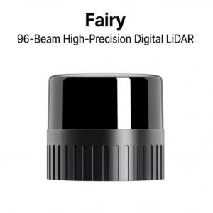
The JT128 from Hesai represents this new approach in a compact package built specifically for mini 3D lidar robotics applications — delivering comprehensive spatial awareness from a single, lightweight sensor unit.
Understanding exactly how that coverage works starts with the geometry itself.
Step 1: Mastering the 360° x 189° Hyper-Hemispherical Field of View
Understanding what makes the JT128 genuinely different starts with unpacking what “hyper-hemispherical” actually means — because it’s not just marketing language. It describes a sensor that sees more of the world than any standard hemisphere would allow.
Breaking Down the 360° x 189° Geometry
A conventional 3D LiDAR sensor typically covers a 360° horizontal sweep paired with a vertical field of view ranging from 30° to 40°** — enough for highway-speed vehicles or open warehouse floors, but dangerously limited in cluttered indoor spaces. The JT128 takes a fundamentally different approach.
According to Hesai Technology’s official product specifications, the JT128 provides a 360° horizontal by 189° vertical field of view, covering nearly the entire sphere around the sensor. To put that in concrete terms: a perfect hemisphere covers exactly 180° vertically. The JT128 exceeds that threshold by 9°, which means the sensor’s coverage actually wraps below the mounting plane on both the upper and lower boundaries. The result is JT128 LiDAR no blind spots in the traditional vertical sense — neither the ground immediately beneath the robot nor obstacles well above it escape detection.
Why ‘Above the Horizon’ Coverage Changes Indoor Robotics
Most LiDAR deployments are engineered around the assumption that threats exist at roughly the same horizontal plane as the sensor. In practice, that assumption breaks down constantly. Hanging electrical conduits, low-clearance doorframes, sloped conveyor systems, and even carelessly placed signage all occupy vertical space that standard sensors simply ignore.

A sensor that can only look forward and sideways is fundamentally incomplete for any robot operating in a human-built environment where infrastructure exists in three dimensions.
With 189° of vertical coverage, the JT128 captures ceiling-mounted obstacles, overhead wires, and angled surfaces without requiring a secondary upward-facing sensor. That eliminates both the hardware cost and the data-fusion complexity of stitching two sensor streams together.
The ‘Mini’ Form Factor and Mounting Flexibility
The compact Mini form factor of the JT128 makes this wide FOV practically deployable. A smaller sensor profile means it can mount lower on a robot’s chassis, closer to the center of mass, or even recessed into the body — without the physical bulk that typically forces engineers into awkward tradeoff decisions between sensor placement and robot balance.
Verification Checkpoint: Calculating Vertical Angular Resolution
- Identify the total vertical span: 189°
- Divide by the number of channels: 189° ÷ 128 channels = ~1.48° per channel
- Compare to a 30°/32-channel sensor: 30° ÷ 32 = ~0.94° — similar resolution, but across a coverage area 6.3× larger
- Confirm: the JT128 delivers broad vertical awareness without sacrificing meaningful angular granularity
That point density across such a wide vertical arc is exactly what enables reliable detection of small, irregularly placed objects — which is precisely what the next section examines in depth.
Step 2: Leveraging 128-Channel Density for Safety-Critical Navigation
Point cloud density isn’t just a spec sheet talking point — it’s the difference between a robot that detects a thin pallet jack leg at 20 meters and one that doesn’t. With the hesai jt128 lidar packing a full 128-channel architecture, the jump in environmental resolution is substantial enough to change what autonomous systems can actually do in the real world.
Why Channel Count Changes Everything
To appreciate why 128 channels matter, consider what lower-density alternatives miss:
| Feature | 16-Channel LiDAR | 128-Channel (JT128) |
|---|---|---|
| Vertical angular resolution | ~2.0° | ~0.2° |
| Small object detection (thin poles, curb edges) | Unreliable beyond 8–10 m | Reliable at extended range |
| Object classification confidence | Low at speed | High, even for compact targets |
| Point cloud richness | Sparse, gap-prone | Dense, continuous surface mapping |
The vertical gaps between scan lines in a 16-channel system create literal blind zones — narrow objects slip right through them. A 128-channel sensor closes those gaps dramatically, resolving objects that would otherwise register as noise or simply not register at all.
The JT128 generates over 3.4 million points per second, producing a data stream rich enough to feed AI classification models with the granular surface detail they need to distinguish a cardboard box from a concrete pillar — or a human leg from a table leg.
Point Density and AI Classification Accuracy
The relationship between point density and classification accuracy is direct: more points per object means more geometric features for a machine learning model to analyze. In practice, a sparse point cloud forces an AI to make probabilistic guesses based on incomplete geometry. A dense cloud lets the model work with actual shape data — edges, curves, and surface normals — that anchor confident decisions. For safety-critical applications like autonomous forklifts or delivery robots navigating crowded warehouses, that confidence gap carries real consequences.
Handling Ghosting and Noise
High-density environments — reflective floors, glass walls, overlapping sensor fields — introduce ghosting artifacts and false returns that can confuse navigation stacks. The JT128 addresses this through its onboard signal processing, filtering spurious returns before they reach the point cloud output. According to Hesai’s official product documentation, the sensor is engineered specifically for the demanding conditions inside industrial and service robotics deployments.
For a deeper look at managing and processing this data downstream, exploring dedicated resources on LiDAR data processing for robotics is worth the time — the quality of the input data the JT128 provides only pays off when the processing pipeline is built to handle it.
Of course, raw detection capability and data quality are only part of the story. Knowing a sensor sees something clearly matters less if the system can’t guarantee it will keep seeing reliably — which is where functional safety standards enter the picture.
Step 3: Integrating Automotive-Grade Reliability (ISO 26262) into Industrial Platforms
Sensor performance means very little if a failure goes undetected. As autonomous robots operate alongside human workers in warehouses, manufacturing floors, and logistics hubs, the stakes of a “silent failure” — where a sensor degrades or stops working without triggering an alert — become dangerously high. This is precisely where ISO 26262 and ASIL B certification shift from automotive compliance checkboxes to mission-critical industrial requirements.
Understanding ISO 26262 and ASIL B in LiDAR Diagnostics
ISO 26262 is the international functional safety standard for electrical and electronic systems in road vehicles, structured around a risk classification framework called the Automotive Safety Integrity Level (ASIL). ASIL ratings range from A (lowest) to D (highest), with ASIL B representing a meaningful threshold — the level at which systems must demonstrate rigorous fault detection, diagnostic coverage, and safe-state response mechanisms.
For a LiDAR sensor like the JT128, ASIL B compliance means its internal diagnostics are engineered to continuously monitor system health and report anomalies before they cascade into navigation errors. In practice, this translates to hardware and software watchdogs that flag degraded performance in real time rather than waiting for a downstream collision to expose the problem.
Why Industrial Robots Now Demand Automotive-Grade Safety
Forklifts and AGVs (Automated Guided Vehicles) were once governed primarily by industrial machinery standards. However, as these platforms become fully autonomous and share dynamic spaces with people, the functional safety gap between automotive and industrial applications has largely closed. A 2-ton autonomous forklift operating at speed carries collision risk comparable to a low-speed vehicle — making automotive-grade safety logic not just preferable, but increasingly expected by integrators and insurers alike.
The jt128 mini 360 x 189 hyper-hemispherical design reinforces this alignment: broad spatial awareness combined with ASIL B diagnostics creates a sensor that’s both perceptually capable and architecturally trustworthy.
Safety Benefits at a Glance
- Fault transparency: Continuous self-diagnostics surface potential failures before they affect navigation decisions
- System-level integration: ASIL B architecture supports clean hand-off into broader FuSa-compliant robot control systems
- Reduced liability exposure: Documented diagnostic coverage supports safety cases required for facility certification and insurance compliance
Verification Checkpoint — FuSa Integration Review:
Before deploying the JT128 within a functional safety architecture, confirm the following:
- Obtain and review the JT128 Safety Manual from the manufacturer — it defines the sensor’s diagnostic coverage metrics and safe-state behavior
- Map the sensor’s ASIL B outputs to your system’s safety goal decomposition, ensuring diagnostic fault signals are wired into the robot’s emergency stop or degraded-mode logic
- Validate that your integration does not exceed the sensor’s assumed safety context (ASIL B does not cover all hazard categories — consult your system safety engineer)
Solid functional safety integration at the sensor layer sets the foundation for the next challenge: maintaining that reliable performance when the environment itself becomes hostile.
Step 4: Optimizing for Adverse Environments and Weather Resilience
Controlled warehouse environments are the exception, not the rule. Robots operating in food processing plants, outdoor logistics yards, construction sites, and cold-storage facilities face conditions that can cripple passive camera systems almost instantly. For hyperhemispherical 3D LiDAR technology to deliver on its promise, it must perform as reliably in a fog-filled loading dock as it does under ideal lab conditions.
Active Light vs. Passive Imaging in Challenging Scenes
The fundamental advantage of active LiDAR over passive camera systems becomes most apparent in low-contrast, low-light, or visually cluttered environments. Cameras depend entirely on ambient light and surface texture to distinguish objects — meaning a dark pallet against a dark floor, or a worker in a gray uniform against a concrete wall, can disappear entirely. The JT128’s active near-infrared pulse technology emits its own light source, measuring return times independently of ambient conditions. Shadows, glare, and overcast skies become irrelevant variables.
“As autonomous systems move into unstructured real-world environments, the ability of sensing hardware to maintain detection accuracy regardless of lighting or atmospheric conditions is no longer a luxury — it is the baseline requirement for safe deployment.”
Filtering Environmental Noise: Dust, Steam, and Rain
Industrial environments generate substantial optical interference — steam from machinery, airborne dust, rain, and reflective surfaces can all corrupt point cloud data. In practice, the JT128 addresses this through multi-return signal processing, which separates genuine object returns from noise-generating particles. Rather than registering a dust cloud as a solid obstacle, the sensor’s algorithms classify and discard low-intensity spurious returns, preserving a clean, actionable point cloud. This distinction is critical for robots operating near conveyor systems, CNC equipment, or outdoor loading areas where visibility is routinely compromised.
Thermal Management for High-Duty Industrial Cycles
Continuous operation generates heat, and heat degrades sensor accuracy over time. The JT128’s thermal management architecture is engineered for high-duty cycle industrial use, maintaining stable performance across extended operational windows without requiring active cooling interventions. This is particularly relevant as the global LiDAR market for high-resolution sensors (100+ channels) is projected to grow at a CAGR of over 25% through 2030, driving demand for sensors that don’t compromise accuracy under sustained workloads.
With environmental resilience confirmed, the practical question becomes execution — and the next section walks through a concrete implementation checklist to get the JT128 deployed correctly from day one.
Implementation Checklist and FAQ
Bringing the JT128 into a real-world robotics platform is straightforward when you follow a structured approach. Whether you’re integrating it into an autonomous mobile robot, an outdoor inspection drone, or a warehouse logistics system, the steps below help ensure a smooth deployment from day one.
Pre-Deployment Checklist
Use this checklist before powering up your system:
- Mounting position confirmed — Center the sensor to maximize the 360° × 189° hyper-hemispherical FOV with no structural obstructions above or below
- Power supply verified — Confirm a stable 9–32V DC input matching the JT128’s operating range
- Cable routing secured — Use strain relief on all connectors to prevent vibration-induced disconnections
- Ethernet interface configured — Assign a static IP and verify packet reception before full integration
- Environmental sealing checked — Confirm IP67 compliance is maintained at all cable entry points
- Time synchronization enabled — Use PTP or GPS-based sync for multi-sensor fusion accuracy
- Firmware version confirmed — Download the latest stable release from the manufacturer portal before deployment
Frequently Asked Questions
Does the JT128 support ROS and ROS2? Yes. The JT128 is compatible with both ROS and ROS2 via standard point cloud drivers. Most teams are operational within hours of initial setup, with launch files and configuration templates readily available in the open-source community.
How does the hyper-hemispherical FOV affect data bandwidth? The expanded vertical coverage does increase point cloud density. In practice, teams should allocate dedicated Gigabit Ethernet throughput and plan for efficient data filtering pipelines — particularly in edge-computing scenarios where processing headroom is limited.
Can it be used for both indoor and outdoor robotics? Absolutely. The combination of automotive-grade lidar reliability and IP67 weatherproofing makes the JT128 equally capable indoors and out. As noted by Dr.ue Industry Expert Analysis, high-resolution LiDAR provides critical redundancy in adverse weather where visual contrast is entirely lost — a decisive advantage outdoors.
What’s the best way to select the right sensor for my specific application? For a deeper comparison framework, explore Choosing the Right LiDAR for Your Robotics Project to align specifications with your use case.
Blind spots in autonomous robotics are an engineering problem with a proven solution. Contact the technical team at lidarstar.com/ for application-specific guidance, integration support, and sensor evaluation units.
Key Takeaways
- Fault transparency: Continuous self-diagnostics surface potential failures before they affect navigation decisions
- System-level integration: ASIL B architecture supports clean hand-off into broader FuSa-compliant robot control systems
- Reduced liability exposure: Documented diagnostic coverage supports safety cases required for facility certification and insurance compliance
- Mounting position confirmed — Center the sensor to maximize the 360° × 189° hyper-hemispherical FOV with no structural obstructions above or below
- Power supply verified — Confirm a stable 9–32V DC input matching the JT128’s operating range