3D LiDAR for V2X and intersection safety is useful because the hardest traffic scenes are not always visible from a single vehicle. A truck can block a pedestrian, a cyclist can appear from behind a parked vehicle, and a turning driver may not see the full conflict zone. Roadside perception adds another view of the intersection before a warning, timing change, or message is considered.
The quick answer is that 3D LiDAR for V2X and intersection safety should be designed as a measured detection-to-message chain. The roadside unit detects objects, tracks their movement, filters false alarms, aligns them to the intersection map, and sends useful information only when the downstream system can act on it. Detection alone is not the same as safer traffic behavior.
Begin With The Conflict Zone
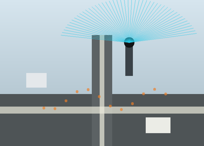
A practical project should map the conflict zone first. That includes crosswalks, turn pockets, bike lanes, bus stops, curb ramps, near-side and far-side pedestrian areas, and any occlusion caused by buildings, trees, parked vehicles, or large trucks. A sensor mounted in the wrong place may see impressive traffic flow while missing the danger point.
For vehicle perception teams, the automotive LiDAR application page is the internal reference. For infrastructure and operations teams, the LidarStar solutions page helps connect the same sensing approach to smart city, security, and industrial monitoring use cases.

Why Roadside 3D Perception Helps
Vehicle sensors move with the vehicle and can be blocked by nearby objects. A roadside 3D sensor can watch the whole approach from a fixed perspective. That does not replace careful vehicle design, but it can add context at intersections where occlusion, mixed traffic, and unpredictable movement create risk.
The U.S. Department of Transportation maintains a current V2X information page describing vehicle-to-everything communication as a way for road users and infrastructure to share safety information. The ITS connected vehicle research area provides broader context for connected vehicle programs and deployment research.
From Detection To Real-Time Messages
A roadside system usually starts with object detection: pedestrians, bicycles, vehicles, work crews, or other moving objects. The system then estimates location, speed, direction, and path. Those observations need to be placed into a map of the intersection before they become useful for connected messages or signal decisions.
Standards matter because every system should not invent its own language. The SAE J2735 standard page is relevant because connected vehicle messages depend on shared definitions. Teams also discuss sensor sharing concepts such as detected objects and roadway participants when designing future infrastructure-to-vehicle workflows.
| Pipeline stage | Roadside question | Validation method |
|---|---|---|
| Coverage | Can the sensor see the conflict zone? | Walk and drive marked paths |
| Classification | Are objects typed consistently? | Review saved events by class |
| Tracking | Are speed and direction stable? | Compare tracks through turns |
| Map alignment | Do detections match lanes and crosswalks? | Overlay on surveyed geometry |
| Message readiness | Is the data timely and actionable? | Measure latency and false alerts |
Latency Is A Safety Design Issue
Intersection data has a short shelf life. A pedestrian can step into a crosswalk in a second, and a turning vehicle can change the risk scene quickly. That means the sensing, processing, networking, and receiving system must be evaluated together. A perfect classification that arrives late may not help the user.
NHTSA explains the safety purpose of vehicle-to-vehicle communication in terms of exchanging information that can support warnings. Infrastructure projects should use the same discipline: define the warning or action first, then work backward to the data quality and timing needed.
LiDAR Data Should Be Anonymous By Design
A useful advantage of 3D geometry is that many traffic applications can operate on positions, tracks, sizes, and movement patterns rather than personal identity. The roadside system can detect a person-shaped moving object in a crosswalk without needing a face or plate. That does not remove every privacy question, but it gives the project a better starting point.
The general vehicle-to-everything concept overview is a helpful non-specialist reference because it separates communications between vehicles, infrastructure, pedestrians, networks, and other road users. In a LiDAR project, those communication paths should be matched to clear events, such as pedestrian presence, near-conflict movement, queue length, or blocked sight lines.
Where Projects Create False Confidence
One common mistake is testing only during light traffic and clear weather. The intersection may behave differently at school pickup, shift change, glare conditions, rain, nighttime, road work, or special events. A pilot should include the hours and conditions that create the real operating concern.
Another mistake is counting detections without measuring usefulness. A system may detect every vehicle but still fail to identify a turning conflict. It may track pedestrians well but align them poorly to the map. It may produce too many alerts, causing drivers or operators to ignore them. Review behavior, not only the sensor feed.
Hardware Placement Checks
For roadside placement, height and angle shape everything. A high mount can reduce occlusion but may create steeper angles for small objects. A low mount can improve detail but may be blocked by vehicles and roadside equipment. The sensor window should stay serviceable, protected, and aligned after wind, vibration, cleaning, and maintenance work.
Use the 3D LiDAR sensor category to compare field of view, range, point density, output format, and environmental fit. Use the LidarStar request page to share intersection sketches, mounting photos, target conflict zones, network constraints, and required output format before choosing a sensor.

Operational Review
Traffic engineering, IT, safety, and maintenance teams should review the same evidence. Traffic engineering cares about conflict points and signal decisions. IT cares about networking and cybersecurity. Safety teams care about false negatives and false alerts. Maintenance cares about cleaning, alignment, and replacement access. A deployment plan that ignores one group will struggle after installation.
The strongest pilot report includes event clips, track logs, latency readings, false alert examples, missed-object examples, weather notes, and maintenance observations. It should say what the system is ready to do now and what needs a longer trial.
Pilot Evidence To Collect Before Scaling
A useful pilot for 3D LiDAR for V2X and intersection safety should be written like an engineering record, not a sales note. Record the test location, sensor height, mounting angle, route or scene boundary, object size, lighting, weather or floor condition, software version, and the exact behavior expected from the system. The notes should be factual enough that another engineer can repeat the test without asking what the first team meant.
Start with a clean baseline, then add ordinary difficulty. For a robot, that might mean a low carton, a reflective panel, a dark object, a narrow post, a person crossing from the side, and a temporary obstruction near the normal path. For a roadside or fixed installation, that might mean a slow walker, a fast bicycle, a turning vehicle, glare, partial occlusion, and a maintenance vehicle parked near the sensor. The test should look like daily work, not a staged demonstration.
Every run should capture three layers of evidence. The first layer is raw or minimally processed sensor data. The second layer is the interpreted result, such as an object, track, zone event, depth map, or filtered cloud. The third layer is the actual behavior that followed, such as a stop, warning, route update, measurement, or message. When those layers are saved together, the team can identify whether a problem came from sensing, processing, or decision logic.
Add one control scene that should not trigger the system. This may be an object outside the route, a person standing in a safe area, a vehicle moving away from the conflict zone, or a surface that should be ignored. Control scenes are useful because they reveal whether the system is merely active or actually selective. A reliable deployment needs both positive detection and calm behavior when nothing important is happening.
Also record the ordinary reset procedure. If the sensor is cleaned, rebooted, remounted, or temporarily disconnected, the team should know how to confirm that alignment and output are still correct. Recovery checks are easy to skip during a pilot, but they become important once the system is maintained by people who did not build it.
| Pilot record | What to write down | Why it matters |
|---|---|---|
| Mounting | Height, angle, bracket, window, and cable route | Explains coverage and repeatability |
| Scene | Route, target object, lighting, surface, and occlusion | Connects data to real conditions |
| Data | Raw frame, filtered output, timestamp, and settings | Keeps debugging evidence intact |
| Behavior | Stop, alert, track, map update, or other response | Shows whether sensing changed the outcome |
| Limit | Missed object, false return, latency, or unstable case | Prevents overclaiming readiness |
Common Mistakes That Hide Weakness
The first mistake is changing too many variables between runs. If the team changes mounting height, filter settings, target position, lighting, and speed at once, the next result is hard to explain. Change one important variable, repeat the same scene, and write down the effect. That slower rhythm usually saves time because the cause of improvement or failure remains visible.
The second mistake is reviewing only successful clips. A successful clip shows potential, but the missed object, false stop, delayed message, noisy depth map, or unstable track teaches the project more. Keep a folder of failure examples and label each one plainly. A later engineer should be able to see what failed, what changed, and whether the change actually solved the problem.
The third mistake is confusing visualization quality with operational readiness. A clean point cloud, neat track line, or attractive depth image is useful only if it supports the decision the machine must make. Ask whether the system saw the object that matters, ignored what should be ignored, responded in time, and recovered naturally. If the answer is unclear, the test is not finished.
Maintenance And Operations Review
A practical sensor installation has to survive routine work. The lens or window must be reachable for cleaning. The bracket must resist vibration and accidental bumps. The cable route must avoid strain, pinch points, and moving parts. The mounting position should not create a new hazard for operators or service staff. These details are not secondary; they decide whether the system stays aligned after the first week.
Operations teams should review the test from their own point of view. Does the robot block an aisle? Does a roadside unit create too many nuisance alerts? Does a fixed sensor require a ladder for cleaning? Does the system behave differently during shift change? Engineers may focus on frames, signals, and filters, while operators notice whether the result fits the work pattern. Both views are required before scaling.
A good review meeting uses the saved evidence rather than memory. Replay one clean run and one difficult run. Show the raw data, interpreted result, and behavior. Ask engineering, operations, maintenance, and purchasing to name one pass condition and one concern. The decision should come from shared evidence, not from the loudest opinion in the room.
How To Compare Candidate Sensors
When comparing candidates for 3D LiDAR for V2X and intersection safety, avoid starting with a single headline number. Range, field of view, angular detail, frame rate, interface, environmental fit, mounting options, and software support all matter, but their importance depends on the scene. A compact indoor robot, a roadside intersection unit, and an embedded near-field sensor do not need the same balance of specifications.
Build a simple comparison matrix from the job. List the objects the system must detect, the farthest and nearest useful distances, the required update timing, the allowed mounting envelope, the environment, and the data format your software can actually use. Then score each sensor against those conditions. This keeps the discussion practical and prevents a strong specification in one area from hiding a weakness in the real task.
If the project has a hard integration constraint, put it near the top of the matrix. A sensor that fits the optical requirement but cannot connect to the available controller may slow the project. A sensor with useful data but an awkward mount may create maintenance problems. A sensor that works indoors but fails in glare may not fit an outdoor or doorway scene. The best choice is the one that matches the whole deployment, not the one that wins one column.
Before the final decision, run one readiness review with the people who will install, operate, and maintain the system. Ask whether the sensor can be mounted without blocking normal work, cleaned without special effort, replaced without redesign, and monitored with the tools already available. A technically capable sensor that creates daily friction will be hard to scale. A slightly simpler setup that the site can maintain may produce better long-term results. That final review often catches practical problems before hardware is ordered for the pilot site and rollout.
Handoff Notes For The Next Engineer
The handoff package for 3D LiDAR for V2X and intersection safety should include the final sensor position, mechanical drawings or photos, cable route, host computer, interface settings, frame names, calibration notes, filter parameters, saved examples, and the reason important choices were made. It should also include the known limits, because those limits are often the first thing a future expansion will encounter.
Do not delete negative results after the system improves. If one mounting angle missed low objects, keep the example. If one filter removed useful edges, keep the before-and-after files. If one lighting condition created noise, save the clip. Negative evidence prevents future teams from repeating the same mistake and helps support staff recognize symptoms when the system changes.
A final acceptance note should separate proven behavior from behavior that still needs a longer trial. Short pilots can validate mounting, coverage, timing, and basic response, but they cannot reveal every shift pattern, cleaning routine, seasonal lighting change, surface condition, or maintenance event. Mark what is ready, what is promising, and what should be monitored. That honesty makes the next deployment stronger.
Conclusion
3D LiDAR for V2X and intersection safety can add a valuable roadside view to connected safety programs when it is treated as a full detection-to-message workflow. Start with the conflict zone, validate coverage and tracking, align detections to the intersection map, respect message standards, and test under real traffic conditions. That is how roadside perception becomes useful infrastructure evidence.
FAQ
Does roadside LiDAR replace vehicle sensors?
No. It adds an infrastructure view that can help with occlusion and shared awareness, especially at complex intersections.
What is the first deployment question?
Define the conflict zone and the action the system should support, such as a warning, signal decision, or operator alert.
Why does map alignment matter?
A detection is more useful when it is tied to lanes, crosswalks, stop bars, and turn paths rather than floating in an unreferenced scene.
Can LiDAR support privacy-conscious traffic monitoring?
Yes. Many applications can use anonymous 3D tracks and object classes rather than personal identity.
What should be included in a site request?
Include intersection drawings, mounting options, target conflicts, operating hours, weather concerns, output needs, and network limits.