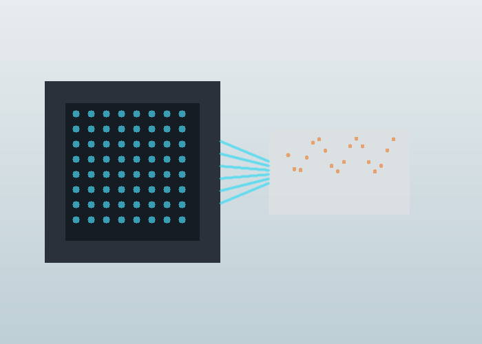
A Flash LiDAR SPAD array is easiest to understand as a depth camera that uses laser time-of-flight principles. Instead of scanning one narrow beam across a scene, a flash approach illuminates an area and receives returns on an array of tiny detectors. That architecture can be attractive when a project needs compact near-field depth, fast snapshots, or fewer moving parts.
The quick answer is that flash LiDAR is not simply better or worse than scanning LiDAR. It trades range, optical power, sunlight handling, resolution, and system complexity in different ways. Engineers should evaluate it from the scene: how close the objects are, how wide the view must be, how much ambient light exists, and whether a snapshot view is more useful than a scanned pattern.
Start With The Architecture
Flash LiDAR sends light across a field of view and measures return time at many receiving elements. In many designs, those receiving elements are related to SPAD technology. A SPAD can detect very small amounts of light, which makes it useful for time-correlated sensing, but the total system still depends on optics, timing electronics, processing, filtering, and environmental design.
The single-photon avalanche diode overview gives a starting definition for SPAD devices, while the avalanche photodiode overview explains the broader detector family. These references are helpful because they separate detector physics from the larger LiDAR product decision.

Why Arrays Matter
An array lets the receiver capture spatial information without a mechanical sweep. Each pixel or detector group can contribute a depth measurement for a region of the scene. That makes flash LiDAR interesting for embedded systems, vehicle corners, docking zones, cabin monitoring, low-speed automation, and compact robotics where packaging matters.
The tradeoff is that illuminating a wide area spreads optical energy. Range and sunlight performance can become harder than in some scanning approaches, especially when the target is dark or far away. The right question is not whether an array sounds modern. The right question is whether the operating scene fits the strengths of the architecture.
Time Of Flight In Plain Language
Time-of-flight sensing measures distance by estimating how long light takes to travel to a surface and return. The time-of-flight camera overview explains the depth-camera concept for a broad audience. In a LiDAR design, timing accuracy, detector sensitivity, pulse shape, and signal processing all affect the final depth estimate.
A practical engineer should look beyond the simple equation. Reflectivity, angle, ambient light, window contamination, temperature, multi-path reflections, and target motion can all change the measured result. This is why lab range claims should be followed by route-style tests using real objects and real lighting.
| Design factor | Why it matters | Field question |
|---|---|---|
| Field of view | Defines the area captured in one snapshot | Does it cover the near hazard zone? |
| Detector array | Shapes resolution and sensitivity | Are small objects still visible? |
| Optical power | Affects return signal | Is performance stable on dark targets? |
| Ambient light handling | Controls outdoor robustness | Does sunlight create noise? |
| Processing latency | Determines action timing | Can the controller use the data in time? |
SPAD Strengths And Limits
SPAD devices are attractive because they can detect very weak optical returns and support precise timing. Research literature, including the SPAD-based LiDAR sensor review and broader SPAD imaging research on PubMed Central, shows how detector design, timing circuits, and array architecture influence LiDAR performance.
The limit is that a detector is not the whole system. A strong SPAD array still needs suitable optics, eye-safety design, calibration, temperature handling, protective windows, and algorithms for separating true returns from background light and unwanted reflections.
Where Flash LiDAR Fits Best
Flash LiDAR often makes the most sense when the scene is near, the required field of view is well defined, and the value of a snapshot is high. Examples include detecting close objects around a slow machine, assisting a docking maneuver, watching a short-range blind zone, measuring package presence, or supporting a compact robot that cannot fit a larger scanner.
For mobile robots, compare the requirement against the robotics LiDAR page and the 2D LiDAR sensor category. A planar scanner may be more efficient for navigation around a flat route. A flash depth sensor may be more useful for close-range volume, docking, or side-zone awareness. The route should decide.
When Scanning Or 3D LiDAR May Be Better
If the project needs longer range, high angular detail over a broad area, strong outdoor performance, or detailed mapping, a scanning or multi-beam 3D approach may be a better fit. That does not make flash technology weak. It means the architecture has a different operating envelope.
Use the 3D LiDAR sensor category when the task needs rich point clouds, height structure, mapping, or larger scene coverage. Use the LidarStar solutions page to frame the application before narrowing the sensor architecture.

Field Test Checklist
A flash LiDAR pilot should include dark objects, bright objects, angled surfaces, glass or glossy edges, direct sunlight or strong artificial lighting, vibration, and the smallest object that matters. It should also include the planned protective window because window material and contamination can change optical behavior.
Run the test at the actual control speed. A sensor that measures correctly while stationary may not support the behavior once the machine is moving. Save raw frames, processed depth maps, false returns, missed objects, and controller responses so the team can decide whether the architecture fits the task.
Procurement Questions
When asking for support through the LidarStar request page, describe the near-field zone, object size, expected range, lighting, mounting limits, output format, frame rate, controller interface, and whether the system must work indoors, outdoors, or both. Include photos from the sensor height, not only from human eye level.
A useful comparison request avoids asking for a universal best sensor. It asks which architecture fits a defined scene. For a Flash LiDAR SPAD array, the best answer depends on field of view, distance, reflectivity, lighting, latency, and packaging constraints.
Pilot Evidence To Collect Before Scaling
A useful pilot for Flash LiDAR SPAD array should be written like an engineering record, not a sales note. Record the test location, sensor height, mounting angle, route or scene boundary, object size, lighting, weather or floor condition, software version, and the exact behavior expected from the system. The notes should be factual enough that another engineer can repeat the test without asking what the first team meant.
Start with a clean baseline, then add ordinary difficulty. For a robot, that might mean a low carton, a reflective panel, a dark object, a narrow post, a person crossing from the side, and a temporary obstruction near the normal path. For a roadside or fixed installation, that might mean a slow walker, a fast bicycle, a turning vehicle, glare, partial occlusion, and a maintenance vehicle parked near the sensor. The test should look like daily work, not a staged demonstration.
Every run should capture three layers of evidence. The first layer is raw or minimally processed sensor data. The second layer is the interpreted result, such as an object, track, zone event, depth map, or filtered cloud. The third layer is the actual behavior that followed, such as a stop, warning, route update, measurement, or message. When those layers are saved together, the team can identify whether a problem came from sensing, processing, or decision logic.
Add one control scene that should not trigger the system. This may be an object outside the route, a person standing in a safe area, a vehicle moving away from the conflict zone, or a surface that should be ignored. Control scenes are useful because they reveal whether the system is merely active or actually selective. A reliable deployment needs both positive detection and calm behavior when nothing important is happening.
Also record the ordinary reset procedure. If the sensor is cleaned, rebooted, remounted, or temporarily disconnected, the team should know how to confirm that alignment and output are still correct. Recovery checks are easy to skip during a pilot, but they become important once the system is maintained by people who did not build it.
| Pilot record | What to write down | Why it matters |
|---|---|---|
| Mounting | Height, angle, bracket, window, and cable route | Explains coverage and repeatability |
| Scene | Route, target object, lighting, surface, and occlusion | Connects data to real conditions |
| Data | Raw frame, filtered output, timestamp, and settings | Keeps debugging evidence intact |
| Behavior | Stop, alert, track, map update, or other response | Shows whether sensing changed the outcome |
| Limit | Missed object, false return, latency, or unstable case | Prevents overclaiming readiness |
Common Mistakes That Hide Weakness
The first mistake is changing too many variables between runs. If the team changes mounting height, filter settings, target position, lighting, and speed at once, the next result is hard to explain. Change one important variable, repeat the same scene, and write down the effect. That slower rhythm usually saves time because the cause of improvement or failure remains visible.
The second mistake is reviewing only successful clips. A successful clip shows potential, but the missed object, false stop, delayed message, noisy depth map, or unstable track teaches the project more. Keep a folder of failure examples and label each one plainly. A later engineer should be able to see what failed, what changed, and whether the change actually solved the problem.
The third mistake is confusing visualization quality with operational readiness. A clean point cloud, neat track line, or attractive depth image is useful only if it supports the decision the machine must make. Ask whether the system saw the object that matters, ignored what should be ignored, responded in time, and recovered naturally. If the answer is unclear, the test is not finished.
Maintenance And Operations Review
A practical sensor installation has to survive routine work. The lens or window must be reachable for cleaning. The bracket must resist vibration and accidental bumps. The cable route must avoid strain, pinch points, and moving parts. The mounting position should not create a new hazard for operators or service staff. These details are not secondary; they decide whether the system stays aligned after the first week.
Operations teams should review the test from their own point of view. Does the robot block an aisle? Does a roadside unit create too many nuisance alerts? Does a fixed sensor require a ladder for cleaning? Does the system behave differently during shift change? Engineers may focus on frames, signals, and filters, while operators notice whether the result fits the work pattern. Both views are required before scaling.
A good review meeting uses the saved evidence rather than memory. Replay one clean run and one difficult run. Show the raw data, interpreted result, and behavior. Ask engineering, operations, maintenance, and purchasing to name one pass condition and one concern. The decision should come from shared evidence, not from the loudest opinion in the room.
How To Compare Candidate Sensors
When comparing candidates for Flash LiDAR SPAD array, avoid starting with a single headline number. Range, field of view, angular detail, frame rate, interface, environmental fit, mounting options, and software support all matter, but their importance depends on the scene. A compact indoor robot, a roadside intersection unit, and an embedded near-field sensor do not need the same balance of specifications.
Build a simple comparison matrix from the job. List the objects the system must detect, the farthest and nearest useful distances, the required update timing, the allowed mounting envelope, the environment, and the data format your software can actually use. Then score each sensor against those conditions. This keeps the discussion practical and prevents a strong specification in one area from hiding a weakness in the real task.
If the project has a hard integration constraint, put it near the top of the matrix. A sensor that fits the optical requirement but cannot connect to the available controller may slow the project. A sensor with useful data but an awkward mount may create maintenance problems. A sensor that works indoors but fails in glare may not fit an outdoor or doorway scene. The best choice is the one that matches the whole deployment, not the one that wins one column.
Before the final decision, run one readiness review with the people who will install, operate, and maintain the system. Ask whether the sensor can be mounted without blocking normal work, cleaned without special effort, replaced without redesign, and monitored with the tools already available. A technically capable sensor that creates daily friction will be hard to scale. A slightly simpler setup that the site can maintain may produce better long-term results. That final review often catches practical problems before hardware is ordered for the pilot site and rollout.
Handoff Notes For The Next Engineer
The handoff package for Flash LiDAR SPAD array should include the final sensor position, mechanical drawings or photos, cable route, host computer, interface settings, frame names, calibration notes, filter parameters, saved examples, and the reason important choices were made. It should also include the known limits, because those limits are often the first thing a future expansion will encounter.
Do not delete negative results after the system improves. If one mounting angle missed low objects, keep the example. If one filter removed useful edges, keep the before-and-after files. If one lighting condition created noise, save the clip. Negative evidence prevents future teams from repeating the same mistake and helps support staff recognize symptoms when the system changes.
A final acceptance note should separate proven behavior from behavior that still needs a longer trial. Short pilots can validate mounting, coverage, timing, and basic response, but they cannot reveal every shift pattern, cleaning routine, seasonal lighting change, surface condition, or maintenance event. Mark what is ready, what is promising, and what should be monitored. That honesty makes the next deployment stronger.
Conclusion
A Flash LiDAR SPAD array can be a strong choice for compact near-field perception, snapshot depth, and designs that benefit from fewer moving parts. It should still be evaluated against the real scene, especially sunlight, dark objects, range, latency, and the smallest feature the machine must detect. Treat the SPAD array as one part of an optical, electronic, and software system, and the selection becomes much clearer.
FAQ
What is a Flash LiDAR SPAD array?
It is a LiDAR architecture that illuminates a field of view and receives depth information with an array of sensitive detector elements, often based on SPAD technology.
Is flash LiDAR the same as a time-of-flight camera?
They share time-of-flight ideas, but LiDAR system design includes laser illumination, optics, timing, processing, and application-specific requirements.
Where does flash LiDAR fit best?
It often fits near-field sensing, compact robotics, docking, blind-zone coverage, and embedded systems with a defined field of view.
What are the main tradeoffs?
Key tradeoffs include range, sunlight handling, detector resolution, optical power, processing latency, and robustness on dark or angled targets.
What should I test before choosing it?
Test the real object sizes, range, lighting, mounting window, vibration, and controller timing in the actual operating scene.