
Not long ago, automotive LiDAR was the exclusive domain of research vehicles bristling with expensive, fragile spinning sensors — impressive at conferences, impractical on driveways. That era is ending fast.
The industry’s central question has shifted from “can it work?” to “can it survive a decade of potholes, temperature swings, and highway grit?” Durability, cost-per-unit, and supply chain scalability have replaced raw point-cloud resolution as the benchmarks that actually matter to procurement teams at OEMs and Tier 1 suppliers.
The numbers reflect that urgency. According to Fortune Business Insights, the global LiDAR market is projected to reach $4.5 billion by 2029, fueled by a 24.5% CAGR driven almost entirely by ADAS integration. That trajectory isn’t speculative — it’s a purchasing signal. When volumes hit mass-production thresholds, the entire supplier ecosystem reorganizes around reliability standards, not laboratory performance.
Consumer vehicles are already feeling the pull. As solid-state designs mature, automakers are embedding LiDAR directly into production trim levels rather than treating it as an aftermarket retrofit — a structural change that demands sensors rated for 10-year operational lifespans, not 10,000-mile demo runs.
Longevity on the road is the new innovation benchmark. The sensor architectures capable of meeting that standard — and the measurement physics behind them — are what separate the contenders from the components. Understanding why requires a closer look at how different sensing technologies actually capture the world around a moving vehicle.
FMCW vs. ToF: Why Instantaneous Velocity is the New Safety Benchmark
As the previous section established, the shift toward production-ready lidar for autonomous vehicles is reshaping what we demand from sensor physics — not just in cost or durability, but in the fundamental quality of information each technology delivers. That’s where the divide between Time-of-Flight (ToF) and Frequency-Modulated Continuous Wave (FMCW) becomes impossible to ignore.
How Each Method Works
Traditional ToF LiDAR operates on a simple premise: fire a laser pulse, measure how long it takes to bounce back, and calculate distance. It’s fast, well-understood, and proven across millions of test miles. However, ToF captures a snapshot — a static point cloud that tells you where an object is, but not how fast it’s moving. Velocity must be inferred by comparing successive frames, introducing latency into a system where milliseconds matter.
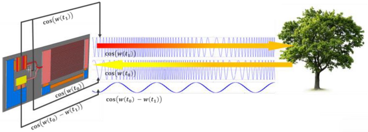
FMCW LiDAR, by contrast, continuously transmits a frequency-chirped laser signal and analyzes the returning wave for both range and frequency shift. The result is a richer data stream — distance and velocity resolved simultaneously, at the pixel level.
The Doppler advantage: every pixel in an FMCW point cloud carries instantaneous radial velocity data, eliminating the frame-to-frame inference gap that leaves ToF systems one step behind fast-moving objects.
As noted by IEEE Xplore research, FMCW LiDAR provides velocity data for every pixel — a distinct advantage over traditional ToF in high-speed highway scenarios.
Predictive Modeling for Oncoming Traffic
This capability has direct consequences for highway autonomy. When a vehicle approaches at 80 mph in an adjacent lane, a ToF system must calculate relative velocity reactively. An FMCW system already knows it — the moment the photons return. That time savings feeds directly into predictive modeling pipelines, allowing the vehicle’s decision layer to anticipate collision risks earlier and with greater confidence.
| Feature | ToF LiDAR | FMCW LiDAR |
|---|---|---|
| Distance measurement | ✓ | ✓ |
| Per-pixel velocity | ✗ | ✓ |
| Doppler shift data | ✗ | ✓ |
| Sunlight interference resistance | Moderate | High |
| Predictive latency | Higher | Lower |
For teams exploring the broader landscape of sensor technologies, this table underscores a fundamental truth: ToF still has a role, but FMCW sets a higher safety ceiling.
What FMCW doesn’t automatically solve, however, is the mechanical reliability problem — an issue that brings us directly to the case for solid-state architecture.
The Death of Moving Parts: The Case for Solid-State and MEMS
The previous section made clear that FMCW’s velocity-sensing advantage is redefining safety benchmarks. But none of that performance matters if the hardware fails at 40,000 miles. That’s the existential problem mechanical spinning LiDAR has always carried — and why solid-state and MEMS-based designs are rapidly becoming the only viable path for lidar in self-driving cars at production scale.
Durability: Eliminating the Mechanical Weak Points
Spinning turrets rely on rotating bearings, slip rings, and motor assemblies — each a potential failure point exposed to constant stress. As McKinsey & Company notes, the transition from mechanical spinning LiDAR to solid-state designs is essential for meeting the rigorous vibration and thermal shock standards required for automotive-grade certification. In practice, a bearing that degrades imperceptibly in a lab can fail catastrophically on a pothole-riddled highway.
Key durability advantages of solid-state designs:
- No rotating assemblies — eliminates bearing wear and motor fatigue
- Rated to survive automotive vibration profiles (typically 5–2000 Hz random vibration)
- Wider operating temperature range, from extreme cold to engine-bay heat
Scalability: Building Sensors Like Circuit Boards
MEMS-based LiDAR mirrors the manufacturing logic of semiconductor production. Components are fabricated at wafer scale, which drives unit costs down dramatically as volume increases — exactly the economics required for high-volume automotive deployment. This scalability is what finally makes widespread Level 3 adoption financially credible.
Scalability benefits include:
- Batch fabrication reduces per-unit cost significantly at volume
- Consistent performance across units due to semiconductor-grade tolerances
- Compact form factors suited to flush vehicle integration
Integration: Higher MTBF, Lower System Complexity
Mean Time Between Failure (MTBF) improves substantially when moving parts are removed from the equation. Solid-state units also simplify the broader sensor architecture, with fewer connectors, reduced wiring harness requirements, and more predictable calibration stability over the vehicle’s lifespan.
However, solid-state designs do introduce their own constraints — particularly around field of view. That limitation leads directly to one of the most pressing unsolved challenges in urban autonomy: what happens in the critical zone immediately around the vehicle, where long-range sensors go effectively blind.
Solving the ‘Near-Field’ Crisis: Blind Compensation Sensors
Long-range lidar is exceptional at what it does—detecting obstacles hundreds of meters ahead at highway speeds. But in dense urban environments, that strength becomes a liability. Stop-and-go city traffic creates a very different threat model: a child darting between parked cars, a cyclist cutting across an intersection, or a low-profile object in the immediate path of a reversing vehicle. These are near-field hazards, and traditional long-range lidar systems are structurally blind to them.
The blind zone problem is real and consequential. Most forward-facing lidar units—including many FMCW LiDAR configurations optimized for range—feature narrow vertical Fields of View (FoV) designed to scan the road ahead at a consistent height plane. That geometry works on open roads. In tight urban geometry, it misses entirely. SAE International specifies that blind-spot and near-field compensation sensors must deliver a vertical FoV of at least 90 degrees to reliably detect small objects in immediate proximity to the vehicle. Most long-range units fall well short of that threshold.
A comprehensive sensor suite addresses this gap with dedicated near-field compensation layers. To meet minimum safety requirements, these sensors must deliver:
- ≥90° vertical FoV to capture ground-level and elevated obstacles simultaneously
- Short to mid-range detection (0.1m–30m) tuned for stop-and-go scenarios
- High angular resolution at close range to differentiate pedestrian legs from static objects
- Low latency data output integrated directly into the vehicle’s central perception stack
- Redundant coverage overlap with primary sensors to eliminate triangular dead zones
The smartest architectures treat near-field sensors not as afterthoughts but as first-class inputs. Understanding how detection priorities shift from mapping to real-time obstacle identification is critical to designing a system that performs across every operational domain—not just the highway.
This layered approach to sensor coverage doesn’t exist in isolation. As autonomous vehicle stacks grow more sophisticated, there’s increasing pressure to make each sensor do more—not just perceive, but also communicate. That convergence is precisely what the next frontier of vehicle intelligence is being built around.
Integrated Sensing and Communication (ISAC): The 6G Future
The previous sections mapped a clear trajectory: sensors are getting smarter, smaller, and more spatially aware. The next leap isn’t just about better hardware—it’s about turning individual sensors into nodes within a living, communicating network.
Integrated Sensing and Communication (ISAC) is the framework driving that shift. Rather than treating sensing and wireless communication as separate engineering problems, ISAC merges them into a unified system that shares spectrum, hardware, and signal processing resources. For autonomous vehicles, this means a solid-state lidar unit could simultaneously map its surroundings and contribute that data to a broader 6G infrastructure in real time.
“ISAC aims to merge spectrum efficiency with high-precision sensing for 6G networks—converging what were once two isolated engineering domains into a single, co-optimized system.” — Huawei Research
The implications for localized mapping and positioning are significant. In a 6G-enabled environment, vehicles won’t rely solely on onboard perception. Instead, lidar-generated point clouds could feed into city-scale digital twins, enabling hyper-accurate positioning that supplements or even cross-validates onboard GNSS and SLAM systems. For Level 3 autonomy, where the system—not the driver—holds situational responsibility, that redundancy isn’t a luxury. It’s a safety requirement.
What makes ISAC particularly compelling is the convergence of sensing and communication KPIs. Latency, bandwidth, and spatial resolution—metrics that once belonged to separate engineering teams—are now jointly optimized. You can explore how multi-channel sensor architectures are already designed with this kind of data-density demand in mind by reviewing high-channel lidar design principles.
In practice, the 6G roadmap accelerates a transition already underway in hardware. The sensor stack is becoming a communication asset—not just a perception tool.
Of course, deploying these advanced sensor systems at scale introduces its own set of challenges, starting with how and where you source the hardware itself.
Procurement Strategy: Bypassing the Tier-1 Markup
The sensor technology breakthroughs covered throughout this article—FMCW coherent detection, solid-state architectures, blind compensation sensors for near-field gaps—mean little if procurement teams can’t source hardware at viable price points. Traditional automotive supply chains add substantial cost at every tier, with markups compounding between the original manufacturer, regional distributors, and authorized resellers. For tech startups and robotics integrators operating on lean budgets, those layers can quietly kill a project.
Factory-direct sourcing changes the equation entirely. According to Lidarstar Market Analysis, direct-factory sales models eliminate intermediaries, allowing high-performance 2D and 3D LiDAR to reach buyers at genuinely accessible price points—without sacrificing specification quality. In practice, that means faster lead times, cleaner warranty chains, and direct access to engineering support when integration challenges arise.
What to Look for in a LiDAR Supplier
Before committing to any vendor, procurement managers should verify the following:
- ✅ Triple-certification compliance — CE, RoHS, and SGS certification ensures the hardware meets global regulatory and safety standards
- ✅ Full product range — Suppliers offering both spinning and solid-state formats let you consolidate vendor relationships across multiple platform types
- ✅ Documented point cloud specs — Range accuracy, FoV parameters, and IP ratings should be listed unambiguously
- ✅ Transparent firmware and SDK support — Integration timelines depend heavily on software access
- ✅ Scalable pricing tiers — Prototype quantities and production volumes should both be accommodated
The smartest procurement teams treat certification as non-negotiable, not a box to check late in the process. CE marking covers electromagnetic compatibility and safety directives across European markets; RoHS restricts hazardous materials; SGS third-party testing adds independent verification that specs are real, not aspirational.
If questions remain about specific hardware trade-offs—such as the difference between 2D and 3D configurations, or how solid-state sensors perform in adverse weather—those practical details are addressed directly in the FAQ below.
Frequently Asked Questions (FAQ)
What is the difference between 2D and 3D LiDAR for robotics?
2D LiDAR scans a single horizontal plane, producing a flat cross-section of the environment — useful for basic obstacle detection on flat floors. 3D LiDAR captures multiple vertical layers simultaneously, building a full volumetric point cloud. For any robot operating in complex or dynamic environments, 3D sensing isn’t optional; it’s foundational. As solid-state designs mature, the cost gap between 2D and 3D solutions is narrowing fast.
Can solid-state LiDAR handle extreme weather conditions?
In practice, no LiDAR technology is fully immune to heavy rain, fog, or snow. However, FMCW architectures offer a meaningful advantage — their coherent detection method filters out ambient noise and crosstalk more effectively than traditional ToF systems, improving signal reliability in degraded conditions.
Why is vertical FoV critical for urban autonomous driving?
Urban environments demand awareness across multiple vertical planes — curbs, pedestrians, overhanging signs, and road debris all exist at different heights. A narrow vertical field of view creates dangerous blind zones. According to LiDAR News, wider vertical coverage directly correlates with safer decision-making at Level 3 and above. Broader vertical FoV isn’t a spec-sheet luxury — it’s a safety requirement.
Key Takeaways
- No rotating assemblies — eliminates bearing wear and motor fatigue
- Rated to survive automotive vibration profiles (typically 5–2000 Hz random vibration)
- Wider operating temperature range, from extreme cold to engine-bay heat
- Batch fabrication reduces per-unit cost significantly at volume
- Consistent performance across units due to semiconductor-grade tolerances