A Flash LiDAR sensor is often considered when a project needs compact close-range perception: docking, machine approach, restricted-zone awareness, small vehicle sensing, or equipment that needs a depth view without a large rotating assembly.
The best way to evaluate it is not to ask whether Flash LiDAR is new or interesting. Ask whether the scene needs a compact depth snapshot. If it does, define exactly where the sensor will be mounted and what the system should do with the depth view.
Quick Answer: Flash LiDAR Is About Close Scenes
Flash LiDAR can be useful when the target zone is near the machine and the system benefits from area-style depth perception. It is different from a long-range scanning approach. The practical question is not which technology sounds better, but which one sees the work zone clearly enough for the system to respond.
For factory equipment, the industrial automation LiDAR section is the most relevant internal starting point. For robots and mobile platforms, the robotics LiDAR application page gives a better context.
Start With The Zone You Cannot Judge Well
A close-range sensing project usually starts with one awkward zone. Maybe a robot must align with a station. Maybe a small vehicle needs awareness near a blind corner. Maybe a machine approaches a fixture and the operator wants earlier confirmation that the space is clear. Flash LiDAR should be tested against that exact zone.
Describe the zone in plain language. How wide is it? How close is the nearest object? Does the object move? Is the background dark, reflective, dusty, or cluttered? Does the sensor need to support a warning, a stop, alignment, or measurement? The answer changes the buying conversation.
The general time-of-flight camera overview is useful because it explains a related way of thinking about depth measurement. The broader LiDAR overview helps connect that idea to laser-based distance sensing.
| Close-range task | What to define | Why it matters |
|---|---|---|
| Docking | Reference surface and tolerance | Prevents repeated alignment errors |
| Blind-zone awareness | Object size and warning distance | Defines useful field of view |
| Machine approach | Stop or slow-down behavior | Connects sensing to control |
| Fixture check | Expected object position | Reduces false confirmations |
| Small vehicle sensing | Mounting height and body blockage | Prevents hidden zones |
Do Not Treat The Image Like A Decoration
A depth image is useful only if the system knows what to do with it. If the project only needs one distance line, another sensor may be enough. If the project needs to understand a small area, a compact depth view can become more valuable. The software rule should be written before the purchase is final.
For example, a docking station may need three rules: find the reference surface, slow before the close zone, and stop if an unexpected object appears. A close-range safety zone may need different rules for a fixed fixture and a moving person. These are not product-table questions. They are application questions.
If the project might need longer-range vehicle perception later, compare it with FMCW LiDAR sensors. Keeping that comparison in the decision helps avoid forcing a close-range sensor into a long-range job.
A Practical Docking And Handoff Scenario
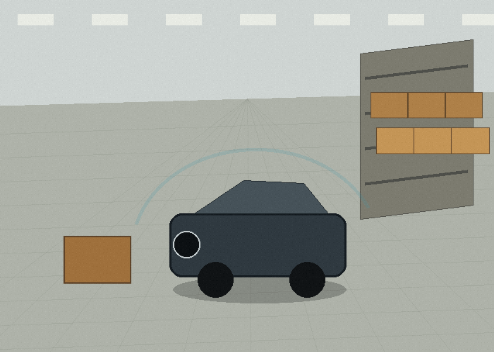
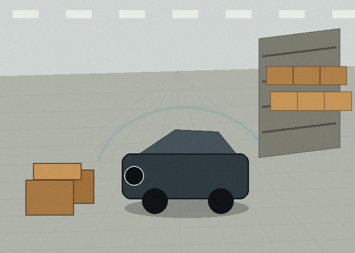
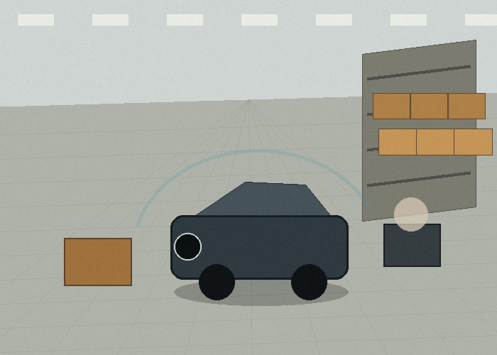
Imagine a compact AMR approaching a handoff station beside a production line. The robot carries a tote, turns into a small docking space, and stops near a fixture. Workers pass nearby, and the station sometimes has a carton leaning into the approach zone. The robot needs to approach smoothly and avoid pushing into anything unexpected.
In this scene, a Flash LiDAR sensor may be tested as a close-zone awareness layer. The test should check whether it sees the station face, the edge of the tote, the floor-level obstruction, and the side object that sometimes leans into the approach path. The sensor does not need to solve the whole navigation system. It needs to make the final approach more reliable.
The external ROS navigation documentation is useful here because docking, local costmaps, and robot behavior all depend on how sensor data becomes a movement decision. Even when the final system is proprietary, the same integration questions apply.
What To Measure In A First Test
Use a short test rather than a long debate. Place the sensor at the planned mounting point. Put the target station in its normal position. Run the approach at slow speed. Move the obstruction slightly between trials. Change lighting if the machine works near a door or window. Record whether the readings remain stable and whether the response happens early enough.
Also test the false-positive side. A sensor that stops the machine too often will be bypassed mentally, even if nobody disables it physically. Define which objects should trigger a response and which objects belong to the normal scene. That rule can be simple at first, but it must exist.
NIST material on mobile robotics test methods is relevant because it pushes teams toward repeatable performance measurement. A small repeatable test beats a polished one-time demo.
| Test | Set up | Pass condition |
|---|---|---|
| Normal approach | Dock clear and robot aligned | Smooth approach and repeatable stop |
| Lean-in object | Carton or tote edge near station | Object noticed before contact risk |
| Lighting change | Door light or shadow across zone | No major loss of useful readings |
| Mounting blockage | Payload loaded at normal height | Sensor view remains clear |
| Maintenance check | Sensor window wiped and inspected | Readings recover after cleaning |
Where Flash LiDAR Fits Beside Other LiDAR Types
Flash LiDAR is not a replacement for every scanner. In many systems, it is a close-range layer. A 2D LiDAR sensor may still handle route scanning. A 3D LiDAR sensor may handle larger scene modeling. A Flash LiDAR sensor may handle the final approach, compact blind zone, or local depth check.
This layered view is why it helps to compare 2D LiDAR sensor options and 3D sensing options with Flash LiDAR side by side. The right answer may be one sensor, but the evaluation should consider the job each layer is supposed to do.
For vehicle-related readers, the overview of advanced driver-assistance systems is a helpful general reference because it shows how sensing becomes warnings or control support. Industrial projects differ, but the sensing-to-response logic is similar.
Build A Small Field Notebook
A good Flash LiDAR sensor project benefits from a small field notebook. It can be a spreadsheet, a shared document, or a printed checklist. The format matters less than the habit. For each trial, record the scene, mounting position, target object, distance, speed, lighting, and whether the system response felt useful.
In a a close-range docking or machine approach zone, people often remember only the dramatic pass or failure. The notebook keeps the quieter details visible. Maybe the sensor worked well with a clean station face, fixture, or nearby obstruction, but struggled when the same object was angled. Maybe it worked in the morning but became noisier near a bright doorway. Those patterns are easy to forget after a long test day.
The notebook should also include photos. Take one wide photo of the whole work area and one close photo of the mounting point. If the sensor is moved, photograph the new location. If the target object is changed, photograph that too. This avoids confusion later when engineering, purchasing, and operations discuss the same test.
Separate Sensor Problems From System Problems
When a test looks bad, do not immediately blame the Flash LiDAR sensor. The problem may be mounting, cable strain, target placement, controller timing, software filtering, or the response rule. A sensor can report useful data while the robot or machine still reacts poorly.
A simple way to separate the problem is to ask three questions. Did the sensor see the object? Did the software interpret it correctly? Did the machine respond in the right way? If the answer fails at the first step, the issue may be sensor placement or sensing limits. If the answer fails at the second step, the issue may be data handling. If the answer fails at the third step, the issue may be control logic.
This matters because late close-zone awareness or unnecessary stopping can have several causes. Buying a different sensor may not help if the real issue is a blocked view or an unclear response rule. On the other hand, software tuning will not solve a scene the sensor physically cannot see.
Define Three Zones Instead Of One Big Zone
Many early tests use one large detection zone because it feels simple. In real work, separate zones are usually more useful. A near zone may require an immediate stop. A middle zone may call for slowdown. A wider awareness zone may simply tell the system to prepare for a possible route change.
For station face, fixture, or nearby obstruction, these zones should be tied to real movement. The near zone should match the distance where contact or alignment error becomes unacceptable. The middle zone should allow a smooth response. The awareness zone should be wide enough to prevent surprise without creating constant false alerts.
Zone design should be tested with people who work near the system. Operators and floor staff know where objects actually appear. They can tell whether a warning feels early, late, or annoying. Their feedback often improves the system faster than a longer engineering debate.
| Zone | Typical purpose | What to verify |
|---|---|---|
| Near zone | Stop or strong warning | No late response at normal speed |
| Middle zone | Slowdown or careful approach | Smooth behavior without harsh braking |
| Awareness zone | Early route or operator awareness | Few nuisance alerts during normal work |
| Ignore zone | Known machine body or fixture | No repeated false trigger from expected structure |
Run The Same Test After A Small Change
One honest test is useful. The same test after a small change is more useful. Move the target object slightly. Change the payload. Shift the mounting angle by a small amount. Run the machine at a slower and then normal speed. These small changes show whether the result is stable or fragile.
In a close-range docking or machine approach zone, fragile results are common. A setup may work when the station face, fixture, or nearby obstruction is centered, then become unreliable when it is near an edge. A sensor may look good when clean, then become less stable after a normal shift of dust, fingerprints, or vibration. Finding that early is cheaper than finding it after rollout.
Do not try to test every possible condition in one day. Choose the five or six conditions most likely to happen during normal work. A realistic test plan is better than a huge test plan nobody completes.
Plan For Maintenance Before The First Rollout
lens access, bracket protection, and routine inspection should be part of the first design discussion. If the sensor window is hard to reach, it will not be cleaned often. If the bracket is easy to bend, the scan or field of view may drift. If the cable is routed through a service area, it may be pulled during maintenance.
Ask who will inspect the sensor and how often. Ask what a normal cleaning method looks like. Ask whether the operator can see obvious damage. Ask whether a replacement sensor can be installed without rebuilding the whole mount. These small questions decide whether the setup remains reliable after the first week.
For a fleet deployment, standardization matters. Use the same mounting reference, cable route, and inspection checklist when possible. If each unit is installed slightly differently, troubleshooting becomes slower and test results become harder to compare.
Make The Decision In Stages
A practical buying decision has stages. First, decide what the sensor must notice. Second, confirm that the planned mounting position can see that zone. Third, test the response with real objects. Fourth, review maintenance. Fifth, decide whether the setup can scale across more machines or routes.
This staged approach keeps the Flash LiDAR sensor decision grounded. It also prevents a common mistake: buying hardware because it sounds advanced, then trying to invent the use case afterward. The use case should lead. The sensor should follow.
How To Review The Result With The Team
After the field test, review the result with the people who will live with the system. Engineers may focus on data quality. Operators may focus on whether the response feels natural. Maintenance staff may notice cleaning and bracket problems. Purchasing may ask whether the same setup can be repeated across future units.
Those viewpoints should not be treated as separate arguments. They are different parts of the same decision. A sensor that is accurate but hard to maintain may still fail in daily use. A sensor that is easy to mount but creates constant nuisance alerts may be ignored. A sensor that works in one carefully prepared scene may need more testing before it becomes a standard choice.
A clear review meeting ends with one of three decisions: proceed with the setup, change the mounting or rules and retest, or choose a different sensing approach. That simple decision structure keeps the project moving without pretending that one test answers everything.
What To Send Before You Ask For A Recommendation
A useful inquiry is short but specific. Send the work scene, the moving object, the target detection zone, the expected response, the mounting space, and the controller interface. The LidarStar quote request page is the best place to include those details because it keeps the product discussion tied to the real application.
Photos help more than long descriptions. A front view, side view, mounting close-up, route view, and one short phone video can reveal blind spots, cable limits, reflection risks, and working distances that are easy to miss in a written message.
If the project has more than one stakeholder, include one sentence about each person’s concern. Operations may care about fewer stops, engineering may care about stable data, maintenance may care about cleaning access, and purchasing may care about repeatability. A recommendation is stronger when it answers all of those concerns without turning the project into a vague wish list. This also makes later comparison between candidate sensors much easier and keeps the project notes readable.
Buying Checklist
| Question | What a useful answer looks like |
|---|---|
| What must the sensor detect? | Objects, distances, surfaces, and the zone that matters |
| Where can it be mounted? | A protected position with a clear view |
| What happens after detection? | Warning, slowdown, stop, map update, or alignment |
| What environment must it survive? | Dust, vibration, light, temperature, or cleaning limits |
| What data does the controller need? | Interface, update rate, coordinate frame, and test method |
FAQ
Is a Flash LiDAR sensor always the best choice?
No. It is the right choice only when its sensing style matches the work scene. The best project starts with the task, not with a product label.
How many field tests are enough?
Run at least one clean test, one cluttered test, one lighting or surface test, and one normal-operation test with the real movement pattern.
Should I compare only range numbers?
No. Range matters, but scan coverage, mounting height, response time, object surface, and integration details often decide whether the sensor works well.
Can one sensor solve every blind spot?
Sometimes, but not always. If the machine or robot has several risk zones, the layout may need multiple sensors or a different sensing layer.
What is the safest next step?
Document the scene, choose a candidate sensor, run a small controlled test, and only then decide whether to scale the same setup.