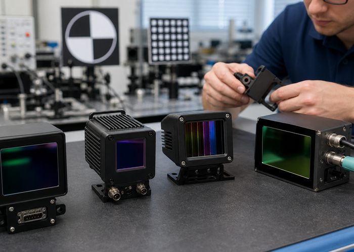
Solid-State LiDAR Types is a practical engineering question, not just a definition. The short answer is that the right sensor is the one that measures the required target with enough range, timing, confidence and software compatibility for the machine to act. Start with the job, validate against authoritative references such as neutral LiDAR technology overview, and compare the result with LidarStar LiDAR sensor engineering resources only after the operating conditions are clear.
For a buyer, integrator or engineering manager, the safest path is to write a small acceptance test before choosing hardware. That test should name the target size, surface, distance, speed, field of view, mounting location, output message and required response. If the project involves robots, vehicles or industrial equipment, LidarStar LiDAR sensor catalog and time-of-flight camera concept give useful context for matching product capability to the real environment.
This guide uses Solid-State LiDAR Types as the organizing question and turns it into a decision workflow. It avoids static price claims and unsupported performance promises because every deployment changes the result. Instead, it focuses on measurable field behavior, practical specifications, current public technical references and the type of evidence a team can reuse during procurement, integration, maintenance and troubleshooting.
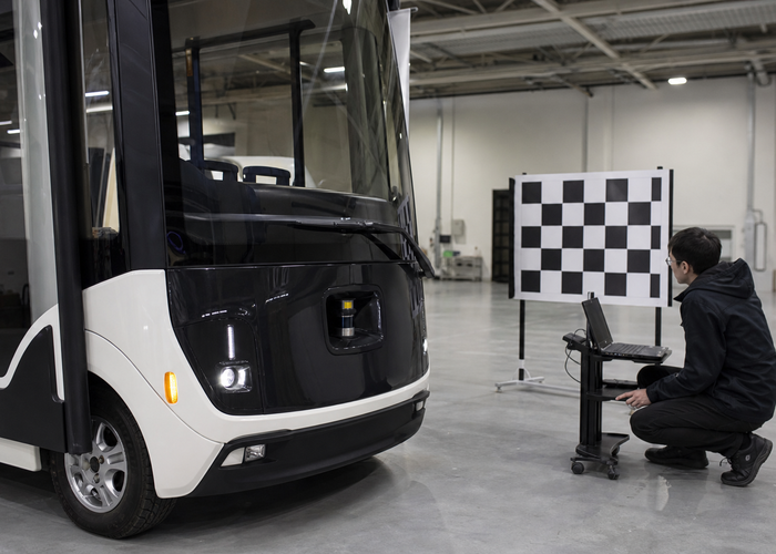
Solid-State LiDAR Types decisions become clearer when the team begins with a measurable job instead of an abstract sensor preference. In this early stage, define the target, distance, motion, mounting height, software output and response time before comparing any specification sheet. A practical team will also keep Doppler effect reference nearby for terminology and measurement context, then map the required behavior to LiDAR sensor product families so the sensor choice stays tied to a real LidarStar application path.
The second discipline is separating the raw measurement from the final machine action. Raw data may look stable, while the filtered output or controller behavior still fails under vibration, glare, occlusion or a low-reflectivity target. This is why a useful test saves raw frames, interpreted objects and the final stop, warning, map update or control message together. The same evidence can be used when discussing 2D LiDAR sensor options, and it should be compared with neutral measurement guidance such as NASA FMCW coherent LiDAR research.
MEMS
MEMS, OPA, Flash and FMCW describe different architecture choices, so the fair comparison starts with the required scene, range and software output. Treat this as a field question. Build a short route or bench setup that includes the target surface, motion, lighting, vibration and software pipeline expected in production. Reference material such as Doppler effect reference helps keep measurement terms grounded, but the pass condition should be written in the language of the machine: detect, localize, slow, stop, map, count or inspect. For teams choosing hardware, LiDAR sensor product families is a practical place to connect that behavior to available sensor families.
A common mistake is approving the first clean demonstration. Clean demonstrations hide low-sun glare, dark targets, glass edges, wet surfaces, airborne dust, angled mounting, cable strain and compute load. Run at least one positive case, one negative case and one degraded case. Save a screenshot only after the raw log and configuration are saved. When an environmental or safety claim matters, cite a source near the claim and then reproduce the condition locally before freezing the design.
The output format also matters. A planner that expects a planar scan will not benefit from a dense cloud until the conversion, filtering and timing are correct. A perception model that expects a cloud needs frame IDs, timestamps, units and invalid-return handling that stay consistent. Before requesting volume deployment, repeat the test after reboot, after cable movement and after a cleaning or service step. That evidence is more useful than a generic comparison table.
Flash LiDAR can simplify near-field coverage
Flash LiDAR can simplify near-field coverage, but teams still need to inspect depth completeness, sunlight behavior and confidence maps. Treat this as a field question. Build a short route or bench setup that includes the target surface, motion, lighting, vibration and software pipeline expected in production. Reference material such as NIST laser scanner calibration experiments helps keep measurement terms grounded, but the pass condition should be written in the language of the machine: detect, localize, slow, stop, map, count or inspect. For teams choosing hardware, 2D LiDAR sensor options is a practical place to connect that behavior to available sensor families.
A common mistake is approving the first clean demonstration. Clean demonstrations hide low-sun glare, dark targets, glass edges, wet surfaces, airborne dust, angled mounting, cable strain and compute load. Run at least one positive case, one negative case and one degraded case. Save a screenshot only after the raw log and configuration are saved. When an environmental or safety claim matters, cite a source near the claim and then reproduce the condition locally before freezing the design.
The output format also matters. A planner that expects a planar scan will not benefit from a dense cloud until the conversion, filtering and timing are correct. A perception model that expects a cloud needs frame IDs, timestamps, units and invalid-return handling that stay consistent. Before requesting volume deployment, repeat the test after reboot, after cable movement and after a cleaning or service step. That evidence is more useful than a generic comparison table.
Comparison Table
Tables are useful only when they help a team make a defensible field decision. Use the table below as a starting point, then replace each generic check with the actual route, surface, speed and software output in your project. Product planning should keep each row tied to a measurable pass condition.
| Architecture | Typical Question | Field Check |
|---|---|---|
| MEMS | Can scanning cover the needed field? | Vibration and edge-of-FOV repeatability |
| Flash | Is near-field depth complete enough? | Sunlight, dark targets and confidence maps |
| FMCW | Is velocity useful and reliable? | Moving-target confidence and logs |
| OPA | Is maturity sufficient for the project? | Availability, qualification and support evidence |
FMCW architectures can add velocity and interference advantages
FMCW architectures can add velocity and interference advantages, yet production readiness depends on implementation, packaging and validation evidence. Treat this as a field question. Build a short route or bench setup that includes the target surface, motion, lighting, vibration and software pipeline expected in production. Reference material such as FDA laser product safety information helps keep measurement terms grounded, but the pass condition should be written in the language of the machine: detect, localize, slow, stop, map, count or inspect. For teams choosing hardware, 3D LiDAR sensor options is a practical place to connect that behavior to available sensor families.
A common mistake is approving the first clean demonstration. Clean demonstrations hide low-sun glare, dark targets, glass edges, wet surfaces, airborne dust, angled mounting, cable strain and compute load. Run at least one positive case, one negative case and one degraded case. Save a screenshot only after the raw log and configuration are saved. When an environmental or safety claim matters, cite a source near the claim and then reproduce the condition locally before freezing the design.
The output format also matters. A planner that expects a planar scan will not benefit from a dense cloud until the conversion, filtering and timing are correct. A perception model that expects a cloud needs frame IDs, timestamps, units and invalid-return handling that stay consistent. Before requesting volume deployment, repeat the test after reboot, after cable movement and after a cleaning or service step. That evidence is more useful than a generic comparison table.
MEMS and other scanning approaches should be checked for field of view
MEMS and other scanning approaches should be checked for field of view, vibration sensitivity, timing and long-term alignment stability. Treat this as a field question. Build a short route or bench setup that includes the target surface, motion, lighting, vibration and software pipeline expected in production. Reference material such as ROS 2 PointCloud2 message documentation helps keep measurement terms grounded, but the pass condition should be written in the language of the machine: detect, localize, slow, stop, map, count or inspect. For teams choosing hardware, robotics LiDAR applications is a practical place to connect that behavior to available sensor families.
A common mistake is approving the first clean demonstration. Clean demonstrations hide low-sun glare, dark targets, glass edges, wet surfaces, airborne dust, angled mounting, cable strain and compute load. Run at least one positive case, one negative case and one degraded case. Save a screenshot only after the raw log and configuration are saved. When an environmental or safety claim matters, cite a source near the claim and then reproduce the condition locally before freezing the design.
The output format also matters. A planner that expects a planar scan will not benefit from a dense cloud until the conversion, filtering and timing are correct. A perception model that expects a cloud needs frame IDs, timestamps, units and invalid-return handling that stay consistent. Before requesting volume deployment, repeat the test after reboot, after cable movement and after a cleaning or service step. That evidence is more useful than a generic comparison table.
Solid-State LiDAR Types decisions become clearer when the team begins with a measurable job instead of an abstract sensor preference. In this middle stage, define the target, distance, motion, mounting height, software output and response time before comparing any specification sheet. A practical team will also keep FMCSA sensor performance guide nearby for terminology and measurement context, then map the required behavior to robotics LiDAR applications so the sensor choice stays tied to a real LidarStar application path.
The second discipline is separating the raw measurement from the final machine action. Raw data may look stable, while the filtered output or controller behavior still fails under vibration, glare, occlusion or a low-reflectivity target. This is why a useful test saves raw frames, interpreted objects and the final stop, warning, map update or control message together. The same evidence can be used when discussing autonomous-driving LiDAR applications, and it should be compared with neutral measurement guidance such as depth sensing and LiDAR video.
OPA concepts are attractive for compact steering
OPA concepts are attractive for compact steering, but buyers should ask what is actually available, qualified and supported for the program timeline. Treat this as a field question. Build a short route or bench setup that includes the target surface, motion, lighting, vibration and software pipeline expected in production. Reference material such as FMCSA sensor performance guide helps keep measurement terms grounded, but the pass condition should be written in the language of the machine: detect, localize, slow, stop, map, count or inspect. For teams choosing hardware, autonomous-driving LiDAR applications is a practical place to connect that behavior to available sensor families.
A common mistake is approving the first clean demonstration. Clean demonstrations hide low-sun glare, dark targets, glass edges, wet surfaces, airborne dust, angled mounting, cable strain and compute load. Run at least one positive case, one negative case and one degraded case. Save a screenshot only after the raw log and configuration are saved. When an environmental or safety claim matters, cite a source near the claim and then reproduce the condition locally before freezing the design.
The output format also matters. A planner that expects a planar scan will not benefit from a dense cloud until the conversion, filtering and timing are correct. A perception model that expects a cloud needs frame IDs, timestamps, units and invalid-return handling that stay consistent. Before requesting volume deployment, repeat the test after reboot, after cable movement and after a cleaning or service step. That evidence is more useful than a generic comparison table.
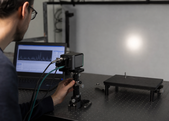
The best architecture is the one that meets the machine action with the fewest integration risks
The best architecture is the one that meets the machine action with the fewest integration risks, not the one with the most fashionable label. Treat this as a field question. Build a short route or bench setup that includes the target surface, motion, lighting, vibration and software pipeline expected in production. Reference material such as neutral LiDAR technology overview helps keep measurement terms grounded, but the pass condition should be written in the language of the machine: detect, localize, slow, stop, map, count or inspect. For teams choosing hardware, industrial automation LiDAR solutions is a practical place to connect that behavior to available sensor families.
A common mistake is approving the first clean demonstration. Clean demonstrations hide low-sun glare, dark targets, glass edges, wet surfaces, airborne dust, angled mounting, cable strain and compute load. Run at least one positive case, one negative case and one degraded case. Save a screenshot only after the raw log and configuration are saved. When an environmental or safety claim matters, cite a source near the claim and then reproduce the condition locally before freezing the design.
The output format also matters. A planner that expects a planar scan will not benefit from a dense cloud until the conversion, filtering and timing are correct. A perception model that expects a cloud needs frame IDs, timestamps, units and invalid-return handling that stay consistent. Before requesting volume deployment, repeat the test after reboot, after cable movement and after a cleaning or service step. That evidence is more useful than a generic comparison table.
Field Checklist Before You Commit
Write the acceptance checklist in plain operational language. Name the object that must be detected, the distance where action must begin, the mounting position, the optical-window condition, the weather or lighting condition and the software output that triggers the final behavior. Keep one clean run and one difficult run in the project folder so later engineering teams can understand the boundary. If the project needs a product shortlist, LidarStar application solutions can turn the same evidence into a focused sensor recommendation.
Do not end the evaluation at the sensor viewer. The useful question is whether the machine makes a reliable decision when the target is partly hidden, moving, dark, wet, angled or close to the field edge. Repeat the route after reboot, after service, after cleaning and after a minor mechanical adjustment. That routine catches fragile integration before the system is copied to more vehicles, robots or sites.
Conclusion
Solid-State LiDAR Types should lead to a repeatable test, not a guess. Use authoritative references, real targets, production mounting, production software and a clear pass condition. When the measured result stays stable across normal and degraded conditions, the sensor choice becomes much easier to defend. That is the practical way to connect Solid-State LiDAR Types with a reliable LidarStar deployment.
FAQ
Is all solid-state LiDAR the same?
No. The term covers several architectures with different tradeoffs. Confirm the answer with a short field check before finalizing the project.
Is Flash LiDAR only for short range?
It is often strongest near field, but each implementation must be tested. Confirm the answer with a short field check before finalizing the project.
Does FMCW solve interference automatically?
It may help, but the practical result must be validated with real sensors and traffic. Confirm the answer with a short field check before finalizing the project.
Should teams choose by architecture first?
Start with the application and use architecture as a way to explain tradeoffs. Confirm the answer with a short field check before finalizing the project.
What should a comparison demo include?
Use the same targets, distances, mounting location and software output for every candidate. Confirm the answer with a short field check before finalizing the project.