Deploying high-temperature industrial LiDAR in a steel mill isn’t an engineering upgrade — it’s a battle against physics that most sensors are simply not built to survive.
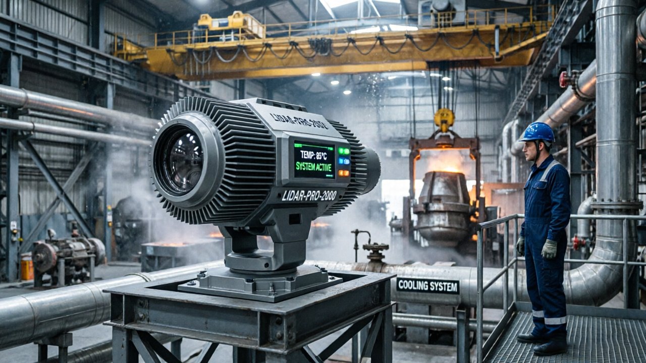
Picture a laser scanner mounted above a continuous casting line. Within minutes of exposure to radiant heat, its housing is warm to the touch. Within an hour, internal temperatures climb past the sensor’s rated ceiling, and the point cloud begins drifting. By the next shift, the unit has failed entirely — not from a direct splash of molten steel, but from ambient thermal energy radiating off metal that sits above 1,000°C.
Standard LiDAR sensors typically operate within a maximum range of 50°C to 60°C, according to Pepperl+Fuchs’ Industrial Vision Division. Smelting floors routinely exceed that threshold many times over near the heat source. That gap — dozens of degrees of headroom against hundreds of degrees of radiant exposure — is the core engineering problem.
dark current is where the damage shows up first. As temperature rises inside the sensor, the APD (Avalanche Photodiode) at the heart of most LiDAR receivers begins generating electron-hole pairs spontaneously, without any incoming photons triggering them. This is dark current, and it scales with heat. As Photonics Media notes, “thermal management in LiDAR is not just about preventing total failure; it is about maintaining the signal-to-noise ratio, as heat increases dark current in photodetectors.” The result is a progressively noisier signal — false returns, missed targets, and degraded range resolution that compounds under continuous thermal stress.
This is the thermal gap: the distance between what a commercial sensor can endure and what a foundry environment actually demands. Bridging it requires more than passive shielding. It calls for active thermal management strategies — starting with the cooling hardware closest to the sensor itself, which the next section examines in detail.
Active Cooling Strategies: Vortex Tubes vs. Thermoelectric Coolers
Keeping sensor electronics alive inside LiDAR for steel mills and foundries comes down to one critical engineering decision: how you actively remove heat from the sensor core without introducing new failure points.
Vortex tubes and thermoelectric coolers (TECs) represent two fundamentally different philosophies — one leverages thermodynamics, the other solid-state physics — and choosing between them shapes everything from enclosure geometry to maintenance schedules.
Vortex tube cooling works by injecting compressed air tangentially into a cylindrical chamber, splitting the airflow into two streams: one hot, one cold. That cold stream — requiring no refrigerants, no compressors, and no moving parts — is then directed into the sensor enclosure. According to EXAIR Corporation, vortex tube systems can reduce internal enclosure temperatures by up to 28°C (50°F), a substantial margin in environments where ambient air already sits well above 60°C. In a high-vibration foundry setting, the absence of mechanical components is not a minor convenience — it’s a reliability multiplier. Rotating fans and pump-driven liquid circuits accumulate bearing wear and seal fatigue rapidly under constant vibration; vortex tubes simply don’t. The tradeoff is compressed air consumption, which must be factored into facility infrastructure planning.
Micro-TEC applications serve a narrower but equally critical purpose: stabilizing the gain of avalanche photodiodes (APDs) inside the LiDAR detector array. APD sensitivity shifts measurably with temperature, so even a few degrees of drift can distort range accuracy. A micro-TEC mounted directly to the detector substrate maintains a stable thermal setpoint regardless of ambient fluctuations — something a vortex tube, which cools the overall enclosure, cannot achieve at that localized level.
traditional liquid cooling, by contrast, introduces tubing, pumps, reservoirs, and leak risk — a combination that makes it largely impractical for mobile robotic platforms navigating foundry floors. The added mass and plumbing complexity conflict directly with the compact, ruggedized form factors that solid-state sensor architectures make possible.
The real question isn’t which single method wins — it’s how the enclosure itself is engineered to work alongside these cooling strategies. That’s where material science and structural design take over.
Designing the Ultimate Protective Housing for Extreme Heat
The housing surrounding a high-temperature LiDAR unit is every bit as critical as the sensor electronics inside it — get the enclosure wrong, and no amount of active cooling will save the system.
Material selection is the first line of defense. Stainless steel alloys, particularly 316L grade, remain the dominant choice for foundry-grade enclosures due to their corrosion resistance and structural integrity above 1,000°F. In practice, raw stainless alone isn’t sufficient near radiant heat sources like open furnaces. Engineers pair the base metal with ceramic-based heat-reflective coatings — similar in principle to the high-emissivity materials used in perlite-based foundry insulation — to redirect infrared radiation away from the sensor face rather than absorbing it.
Double-walled construction takes this further. A standoff air gap between an outer reflective shell and an inner insulated cavity acts as a thermal buffer, slowing the rate at which ambient radiant energy reaches the sensitive optics and electronics inside. This technique reduces peak internal temperatures by a meaningful margin, buying critical headroom for the industrial sensor cooling solutions — whether vortex tubes or thermoelectric coolers — discussed in the previous section.
Hermetic packaging addresses a failure mode that heat alone doesn’t explain: internal oxidation. In steel and foundry environments, corrosive gases like sulfur dioxide penetrate conventional enclosures and degrade laser diodes and photodetectors over time. Hermetic sealing methods, such as those developed by SCHOTT for photonic components, create an inert internal atmosphere that halts oxidation before it starts — a standard referenced widely across EPIC Photonics guidelines.
Key material requirements for a compliant protective housing include:
- 316L stainless steel body for corrosion and structural performance
- Ceramic or metallic heat-reflective coatings on external surfaces
- Double-walled construction with a ventilated air gap
- Hermetic seals on all optical apertures and cable penetrations
- Compact, modular form factor to integrate precision mid-range sensors without extending exposure surface area
Fitting precision mid-range sensors — typically operating in the 0.5–30 meter range relevant to slag monitoring and ladle positioning — into compact housings keeps the enclosure footprint small, which directly reduces the thermal load the cooling system must manage. Smaller external surface means less radiant absorption.
What no housing material can fully solve, however, is the challenge of keeping the optical window clean in an environment filled with conductive metallic dust — and that’s where the engineering logic shifts from passive shielding to active protection.
The Role of Positive Pressure and Air Purge Systems
Controlling the optical environment around a LiDAR sensor is just as critical as controlling its thermal environment — and in a steel mill or foundry, that means fighting a constant battle against conductive metallic dust.
Conductive metallic particulate is one of the most destructive contaminants a LiDAR system can face. When iron oxide, carbon, and fine slag particles settle on an optical window, they don’t just scatter the laser beam — they create signal “ghosting,” where false returns register at near-zero range, and progressive attenuation, where return signal strength degrades silently over time. Unlike ordinary industrial dust, metallic particles conduct electricity, absorb infrared wavelengths, compounding both the optical, and electrical risk to exposed sensor components. Understanding how to protect LiDAR from extreme heat is only half the engineering challenge; protecting the optical path from particulate contamination is the other half. Air purge nozzles create a protective air curtain that physically prevents particles from reaching the sensor window. The mechanics work like this: filtered, dry compressed air is channeled through a precision-machined annular nozzle ring seated around the optical aperture. As air exits the nozzle, it forms a laminar curtain flowing across the face of the window at a controlled velocity — typically optimized to shear away approaching particles without creating turbulent backflow that could draw contamination inward. According to Sick Sensor Intelligence and reporting in Bulk Solids Handling Journal, positive pressure air purge systems are the most effective method for preventing microscopic dust and metallic particles from settling on LiDAR optical windows.
Maintaining positive internal housing pressure reinforces the air curtain’s effect. By keeping the pressure inside the LiDAR enclosure slightly above ambient — even just a few millibars — any micro-gap or seal imperfection becomes an outflow point rather than an ingress point. Particulates simply cannot migrate upstream against a sustained pressure gradient.
The downstream benefit is a meaningful reduction in maintenance cycles. Automated purge systems that run on timed intervals or contamination-triggered sensors can keep optical surfaces clean without manual intervention, extending the time between scheduled shutdowns. This matters enormously on a continuous casting line where unplanned downtime carries a steep cost. Of course, the purge system protects the window’s outer surface — but the window material itself must also withstand the thermal shock of the foundry floor, a challenge the next section addresses in detail.
Optical Integrity: SCHOTT Glass and Anti-Reflective Coatings
Optical clarity under extreme thermal stress is one of the most underappreciated challenges in LiDAR protective housing design — and one of the most consequential to get right.
Standard glass simply cannot survive a foundry environment. Common borosilicate or soda-lime glass cracks under rapid temperature swings because its thermal expansion coefficient is too high to handle the shock. In steel and smelting operations, surfaces near furnace openings can cycle from ambient temperatures to over 600°F in seconds. That kind of thermal gradient creates internal stress fractures that compromise both structural integrity and optical transmission — often simultaneously.
SCHOTT glass — particularly grades like BOROFLOAT 33 and N-BK7 — addresses this limitation through its exceptionally low thermal expansion and high chemical resistance. These properties allow the window to endure repeated thermal cycling without delaminating, crazing, or clouding, which is critical when the sensor window is a permanent part of the protective enclosure rather than a replaceable consumable.
Transmission efficiency, however, is only partly a function of glass type. Thick protective windows inevitably attenuate the outgoing laser pulse and the returning echo. Balancing window thickness against signal loss is a genuine engineering tradeoff — thicker glass offers more mechanical protection but introduces measurable attenuation, particularly at the 905nm, and 1550nm wavelengths most industrial LiDAR systems use. As JNS Glass notes, lidar-specific custom anti-reflective coatings are required to maintain transmission efficiency when sensors are placed behind thick protective windows. Without wavelength-matched AR coatings, Fresnel reflections at each glass surface can reduce signal return by several percent per interface — enough to degrade range accuracy in dusty or smoke-filled smelting environments. In practice, the optimal solution pairs a thermally stable SCHOTT-grade substrate with a dual-sided AR coating tuned specifically to the sensor’s operating wavelength. This combination keeps transmission losses below acceptable thresholds while maintaining the mechanical durability the environment demands. Engineers specifying these windows should also consider how coating durability holds up against airborne particulate abrasion — a factor that becomes especially relevant in the ladle positioning and furnace monitoring applications explored in the next section.
Case Study: Ladle Positioning and Furnace Monitoring
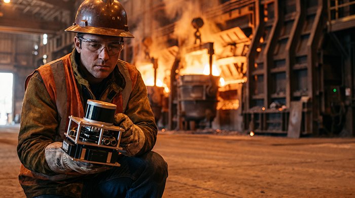
Thermal protection is what separates a LiDAR deployment that lasts years from one that fails in weeks — and nowhere is that contrast sharper than in active smelting zones.
Automated ladle tracking is one of the most compelling real-world applications for 3D LiDAR in steel production. Ladles carrying molten metal at temperatures exceeding 2,900°F must be positioned with millimeter accuracy before pouring. Traditional optical or camera-based systems degrade rapidly under radiant heat and particulate contamination. 3D LiDAR, when housed in a properly engineered thermal enclosure, delivers continuous point-cloud data that allows automated cranes and transfer cars to position ladles precisely — without placing workers in the blast zone. This directly addresses what ASTRI and IMV Tech have highlighted: high-precision mid-range LiDAR is increasingly deployed in hazardous zones where human presence is restricted due to heat.
Furnace slag monitoring is a second high-value use case. Slag accumulation inside an electric arc furnace directly affects melt quality and energy efficiency. Deploying a mid-range LiDAR sensor above the furnace opening — protected by the kind of SCHOTT glass optics and positive-pressure purge systems covered earlier — enables real-time volumetric mapping of slag levels. Operators receive actionable data without manual inspection. According to ITP research on advanced melting technologies, optimizing melt cycles can reduce energy consumption significantly, which translates directly to lower CO2 emissions per ton of steel produced.
Understanding LiDAR systems and how to keep them cool is ultimately what makes these deployments viable long-term. Without active cooling, positive-pressure protection, and hardened optics, sensor lifespan in these environments drops from years to weeks. The thermal engineering solutions discussed throughout this article aren’t optional — they’re the foundation.
As these hardware protection strategies become clearer, the next logical question is which LiDAR architecture — solid-state or mechanical — is best suited for different zones within a steel or foundry facility.
Selecting the Right Hardware: 2D vs. 3D for High-Heat Zones
Choosing the wrong LiDAR architecture for a high-heat industrial environment doesn’t just limit performance — it accelerates failure and inflates replacement costs dramatically.
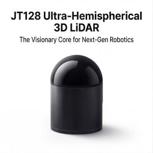
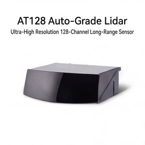
The foundational rule is straightforward: match sensor complexity to the actual task. Industrial-grade LiDAR for high ambient environments often requires specialized 2D navigation systems or 128-channel 3D units depending on the data density the application demands. Getting that call wrong at the procurement stage creates expensive downstream problems.
2D time-of-flight (TOF) sensors are the workhorses of simpler industrial navigation tasks — overhead crane positioning, conveyor tracking, and ladle detection along a fixed axis. They generate a single horizontal plane of distance data, which is computationally lean and thermally forgiving. When the operational goal is “detect object at distance X along path Y,” a 2D system is often the smarter, lower-cost choice. Deploying a high-channel 3D unit for that task is over-engineering with real thermal and budgetary consequences.
Mechanical 3D LiDAR, however, introduces a significant vulnerability in heat-heavy zones. Rotating assemblies — motors, bearings, encoder wheels — are the first components to degrade when ambient temperatures climb above 70°C for sustained periods. Vibration from heavy equipment compounds wear further. In practice, mechanical units in foundry environments often require replacement cycles measured in months rather than years. This is precisely where solid-state alternatives gain their advantage: no moving parts means no heat-accelerated mechanical wear, and no moving parts also means the system is naturally more resistant to the particulate ingress common in smelter environments.
Solid-state and flash LiDAR designs don’t eliminate the need for thermal housing — they simply remove one major failure vector. The sensor itself still requires proper enclosure engineering, including the LiDAR SCHOTT glass windows and anti-reflective coatings discussed earlier in this article. However, the absence of rotating components means these systems tolerate both vibration and sustained heat exposure with considerably greater reliability.
One often overlooked factor is the value of technical consulting before committing to a high-channel system. A 128-channel unit capable of producing dense 3D point clouds may seem like future-proofing, but without application-specific calibration guidance, the data overhead can overwhelm edge computing infrastructure, and complicate integration. Factory-direct hardware procurement paired with upfront engineering consultation — rather than off-the-shelf purchasing — is the approach that consistently reduces both initial cost and long-term failure rates in demanding deployments. Matching sensor architecture to environmental realities is the first decision in building a system that lasts. The next step is distilling those decisions into a clear, actionable framework — which is exactly where the final takeaways come in.
The Bottom Line: Key Takeaways for Industrial LiDAR Protection
Deploying LiDAR in steel and foundry environments comes down to one principle: thermal management is a prerequisite for data integrity, not an optional upgrade.
As Laser Focus World consistently notes across high-precision industrial applications, the sensors that survive are the ones engineered around heat from day one — not retrofitted with protection after the first failure.
Active cooling is non-negotiable above 70°C. Vortex tube coolers remain the most practical solution in environments where compressed air is already available, delivering meaningful temperature reduction without electricity, moving parts, or refrigerants. When ambient heat climbs beyond that threshold — which happens routinely near tap holes, ladle transfer stations, and furnace mouths — passive thermal management simply cannot keep sensor electronics within their rated operating window.
Positive pressure air purging deserves equal priority. Metallic dust in foundry air isn’t just an optical problem — it’s a slow accumulator that eventually bridges electrical contacts and abrades optical surfaces. Continuous filtered airflow through the sensor housing prevents particulate ingress at the source, which is far more effective than periodic cleaning after contamination has already occurred.
Signal integrity depends on what stands between the laser and the environment. Hermetic packaging stops moisture and corrosive gases from reaching internal optics, while anti-reflective coated glass maintains transmission efficiency even as surface temperatures fluctuate. For precision mid-range LiDAR applications — where accurate distance data at 5–30 meters determines ladle positioning or pour timing — any degradation in optical clarity translates directly into positioning errors with real safety consequences.
Hardware selection should prioritize long-term thermal stability over raw range specifications. A sensor rated for 200-meter range that drifts under sustained thermal load is less valuable than a shorter-range unit with a stable, repeatable output across the full operating shift. Solid-state architectures, in particular, have demonstrated advantages in vibration-heavy heat zones — a point explored further in the next-generation sensing platforms developed for demanding industrial and autonomous applications.
These principles aren’t theoretical. They reflect what consistently separates reliable deployments from expensive failures. The questions that remain — about LiDAR behavior through smoke, maintenance intervals, and architecture trade-offs — are exactly what the next section addresses directly.
Frequently Asked Questions: High-Temp LiDAR Deployment
Deploying LiDAR in steel mills and foundries raises engineering questions that standard spec sheets rarely answer — here are the most critical ones.
Can LiDAR see through flames or heavy smoke?
Not reliably without mitigation. Open flames and dense particulate smoke scatter and absorb near-infrared wavelengths, causing point cloud dropout in the affected zone. In practice, longer-wavelength systems (1550 nm) perform better in smoky conditions than 905 nm alternatives, but neither penetrates thick combustion plumes without signal degradation. The engineering solution isn’t a more powerful emitter — it’s strategic sensor placement combined with air purge nozzles that clear the optical path continuously.
What is the maximum ambient temperature a cooled housing can handle?
Standard LiDAR units are rated from -40°C to 85°C by most industry specifications, meaning anything above that threshold requires an active thermal management solution. Well-engineered liquid-cooled enclosures with secondary insulation layers can sustain sensor operability in ambient environments reaching 200°C–250°C. Beyond that range, standoff distance, radiant shielding, and heat sink staging become mandatory rather than optional.
How often does an air purge system require maintenance? A common pattern is quarterly inspection of nozzle orifices and filter cartridges in moderate-dust environments, dropping to monthly checks on high-particulate lines like tapping floors or shake-out stations. Clogged purge lines are a leading cause of premature optical window contamination, so flow pressure monitoring with automated alerts is worth the added cost.
Is solid-state LiDAR better for high-vibration heat zones? Yes — and the advantage is significant. Solid-state architectures eliminate the rotating mirror assemblies that mechanical units rely on, removing the primary vibration failure point. As discussed in reliability research for demanding environments, solid-state designs offer substantially higher mean time between failures under sustained mechanical stress. For foundry cranes, continuous casters, and mold-handling equipment where vibration is constant, solid-state sensor architecture is the correct default choice — not a premium upgrade.